Proto 48 #6 Turnout
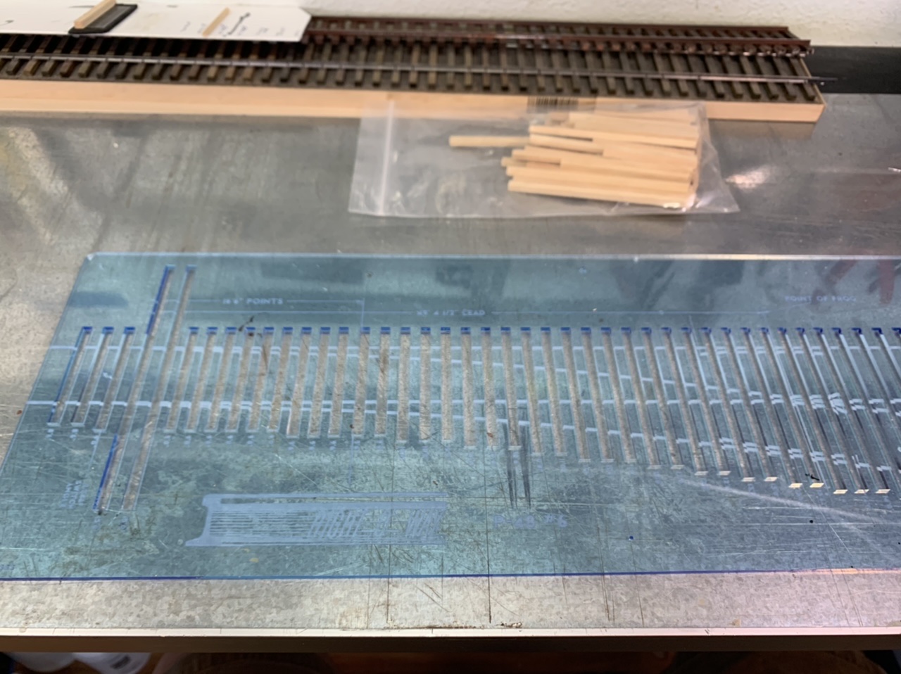
A few months ago I saw Shawn Branstetter”s Building a Right O’ Way Switch Kit post in his Shortline Modelers Blog and really wanted to try it out. The kits were not on the Right-O-Way website, so I reached out to Jay Criswell to see when I could get one. Luckily Jay had some in stock so I immediately jumped on a #6 turnout kit, with ties & details as well as the tie placement template. $100 for the skeleton (rail, points, throw bars, frog, guardrails all held together by pcb ties soldered to the top of the rails). $25 for the detail kit (which is basically the tie plates, gauge plates & rail braces). $7 for pre-cut ties. $40 for the tie placement template which is a sturdy acrylic? reversible and reusable template. I also purchased 800 spikes for $6.25.
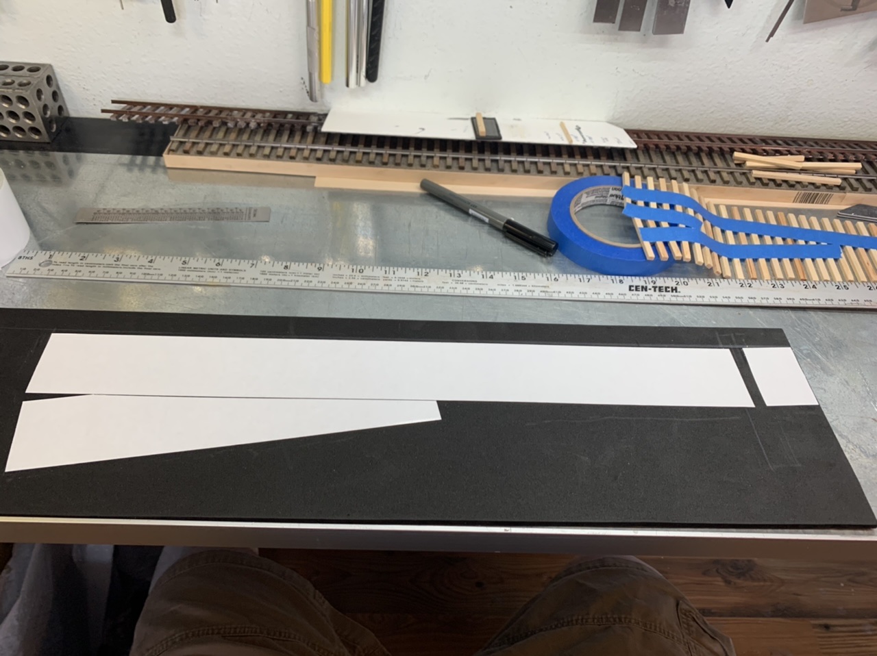
It took a few weeks to get started on this build this turnout. Partly because of time constraints but also because I was trying to come up with the best substrate to build the turnout on. I wanted something that was lightweight, durable, wouldn’t warp and could take glue, tape and paint . I had built a P48 turnout using cork faced foamboard a few years ago, but I had trouble sourcing the same product.
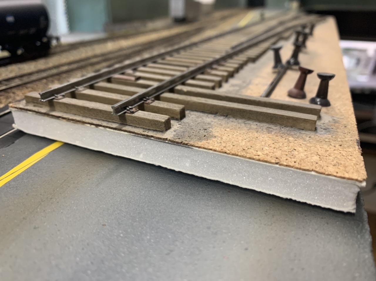
I found 10mm EPS foam at the craft store and thought it would be a a great solution. Sold as cos-play foam, EPS is a semi-rigid lightweight craft foam. EPS foam tested well and seemed to fit all my desires it was lightweight, I could adhere ties to it with double sided tape, as well as super glue, and was easy to paint. The one thing I didn’t think to test was how well I could spike ties on this semi-rigid substrate. Also, it doesn’t hold spikes. I’ve seen many discussions about how some material holds spikes and didn’t really understand what all the fuss was about. Now I do. Spikes seem to float right up out of position with EPS foam.
The Build
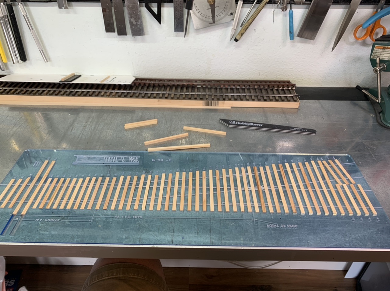
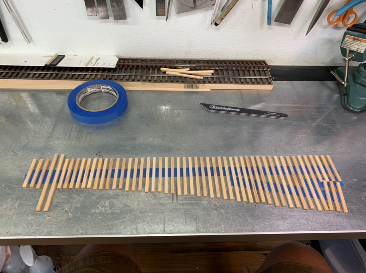
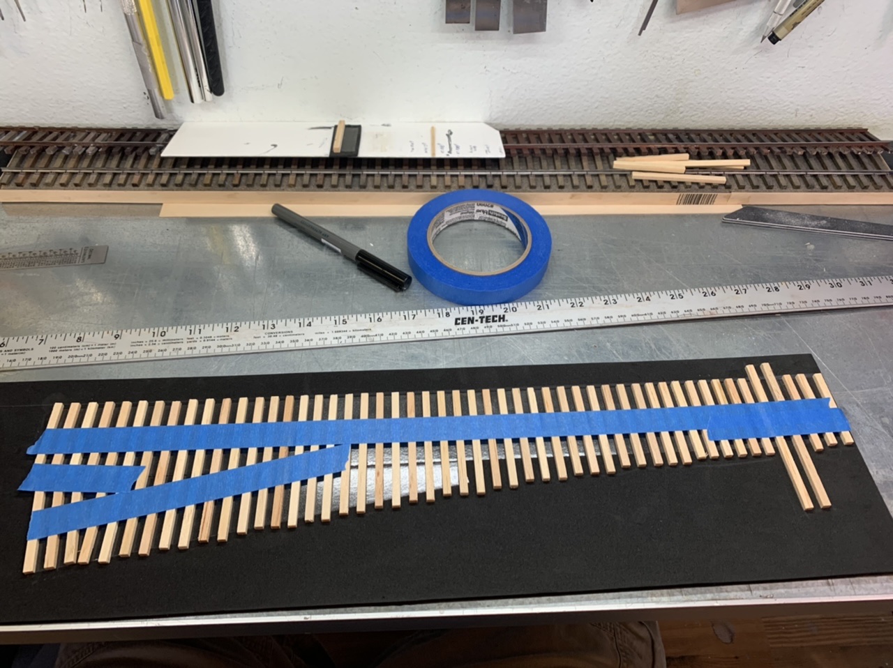
This whole portion of the build took 1 hour! The pre-cut ties and template saved me a ton of time and effort, my previous turnout took several days to get to this point as I measured each tie distance and cut each tie to length.
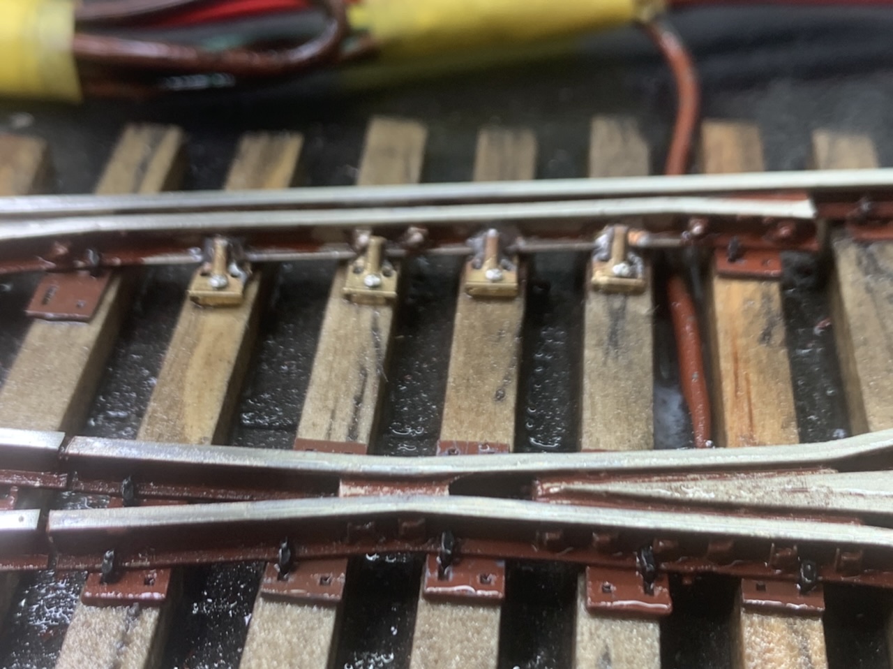
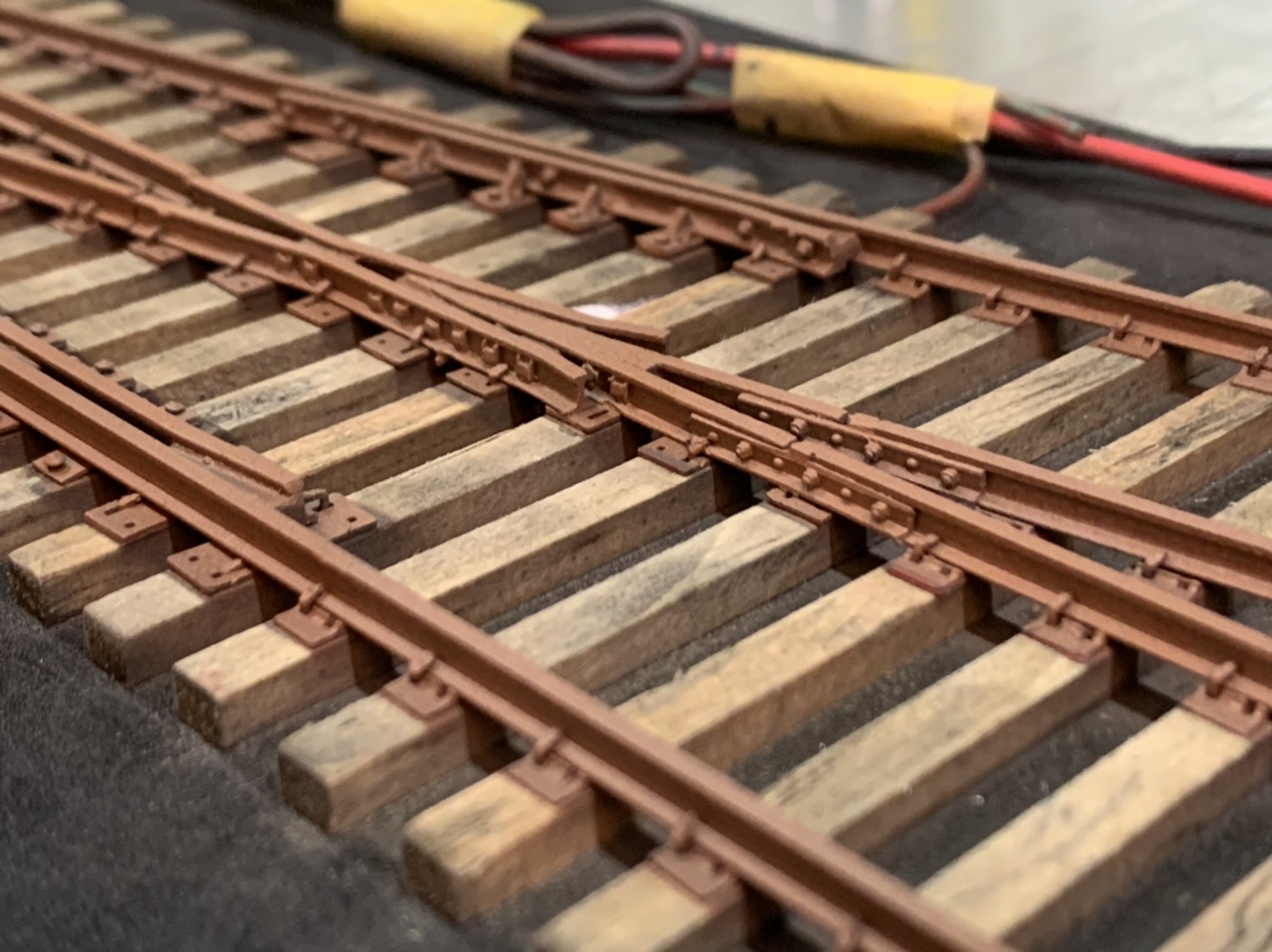
My most time consuming portion of any turnout I’ve built has been tie placement and spiking. While this method offers no way to speed up the spiking (that I’ve figured out) it does really help speed up tie placement. And that was the key benefit I was hoping to get from constructing a turnout using this method. Essentially I was able to use the skeleton and the pre-laid ties as a template to glue most of the tie plates into place before spiking. I also took a HUGE tip from Shawn Branstetter and soldered the brass parts into place first. I also took this opportunity to solder feeders to the rail.
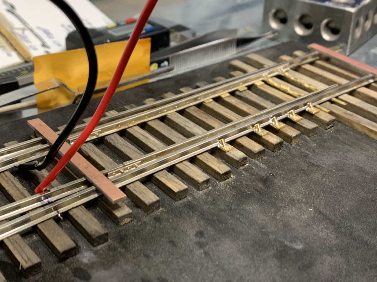
I used a rubber cement product called GS Hypo Cement to attach the tie plates its somewhat flexible, can be cleaned with alcohol, and can be pried up using a chisel blade without any damage to the ties. This system worked pretty good, but I messed up and didn’t check the gauge as I was gluing the tie plates down. The gauge of the skeleton wanders some in the long stretches between the soldered joints which seems obvious now, but for some reason I wasn’t expecting that and didn’t bother to check the gauge as I was gluing the tie plates down. No big problem, I just pried them up as I was spiking and spiked them into gauge.
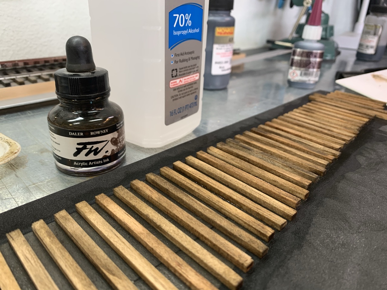
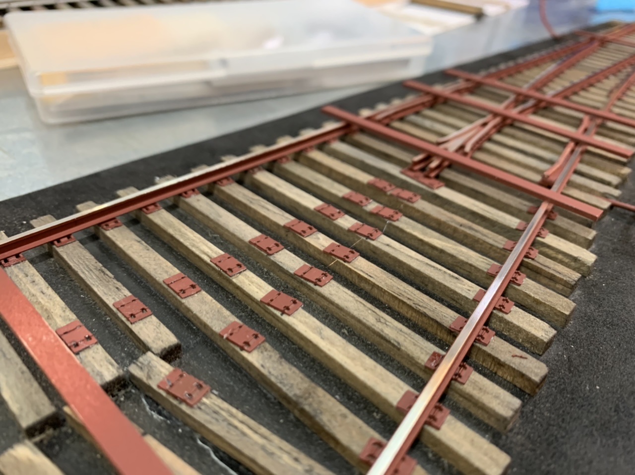
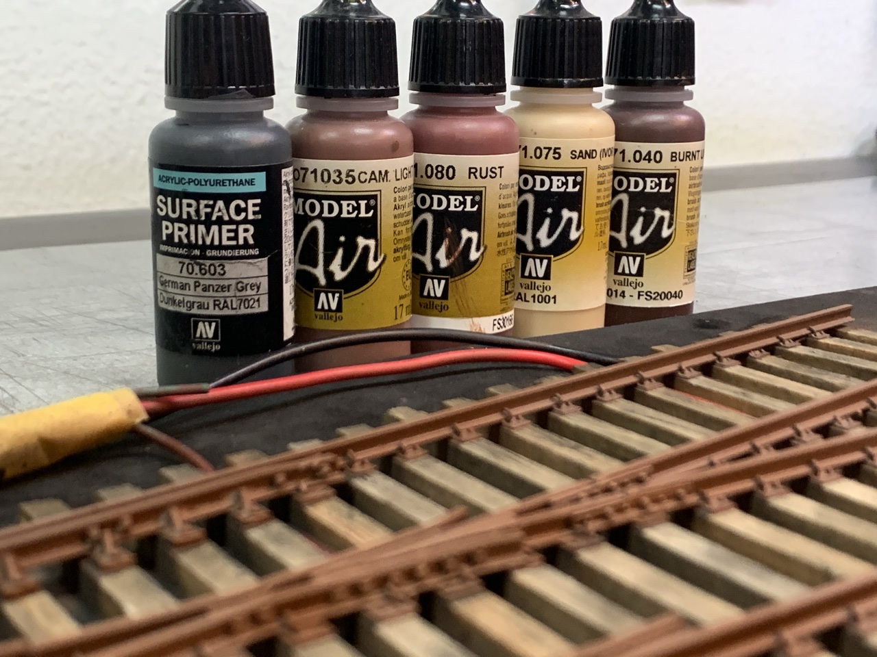
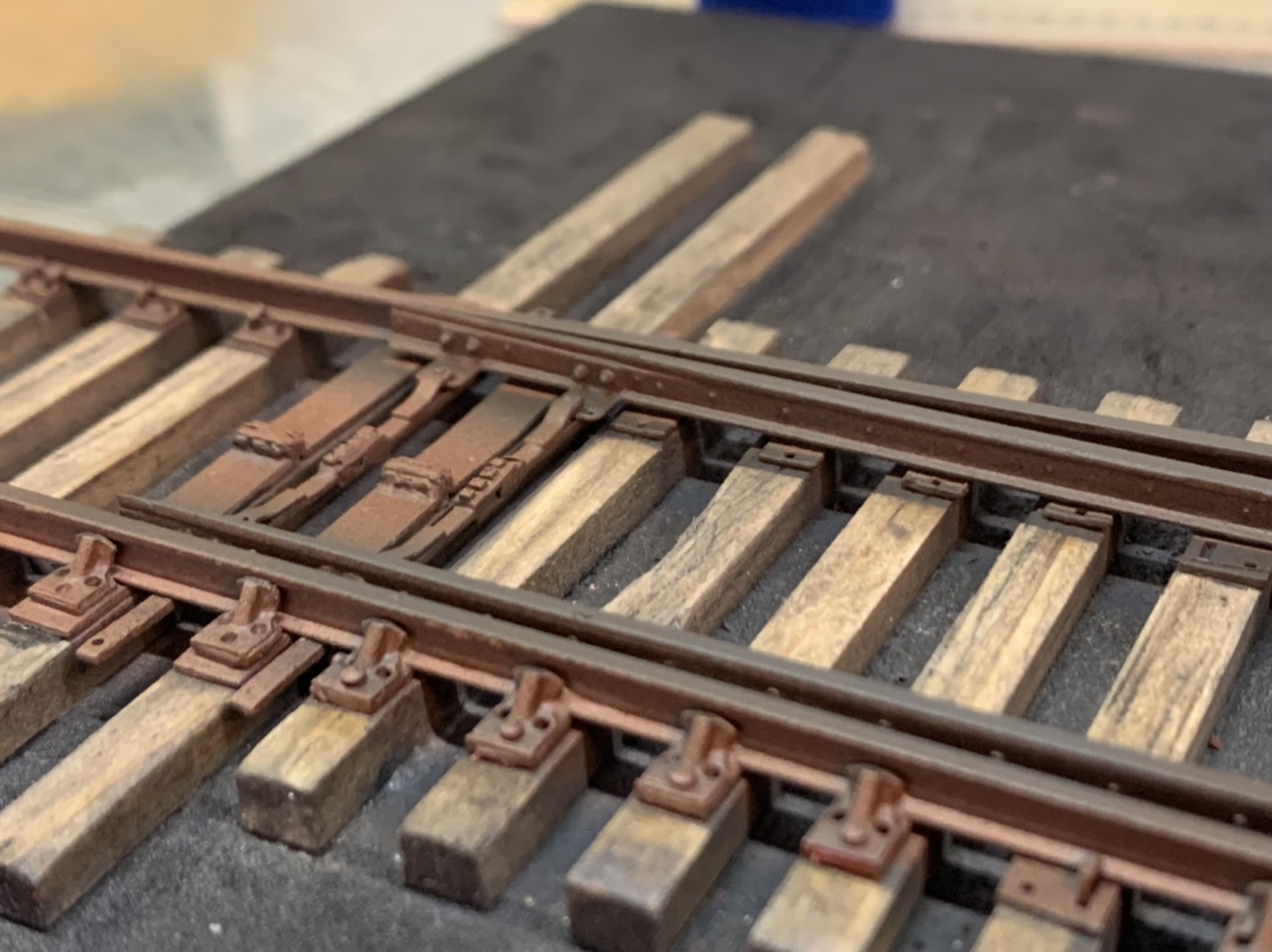
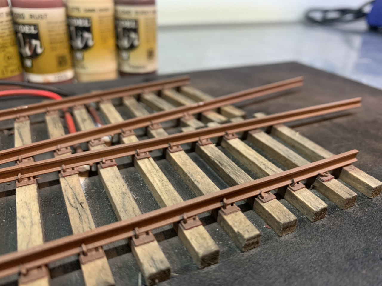
Another time saving idea I considered was painting. I already paint my tie plates while they are on the sprue. Painting the rail before mating it with the ties seemed like it would be a big benefit. After soldering on the rail braces I painted the skeleton a Rust-oleum red/brown primer color.
Once I had the basic tie plates installed and the rails painted I began spiking. I used the P48 track gauge as I spiked along to make sure I was in gauge or to see if I needed to make adjustments. This is where I realized that EPS foam is not a suitable roadbed. As I was spiking, the EPS foam was not rigid enough to withstand the force and frequently just collapsed beneath the pressure. I also realized the Micro-Engineering spikes were not my cup of tea. The head is too long & they frequently bend along the shaft. They are also ribbed (I imagine that feature was to help them hold), but the they don’t hold well. And they frequently destroy the ties you are spiking into.
I also experimented with:
- Peco spikes – way too large
- Walthers/Shinohara code 70 spikes – awesome, but too rare to use on this experimental build (thank you Jay for sending me some)
- P87 stores spikes – really good, but the shank doesn’t correspond with the opening of ROW tie plates.
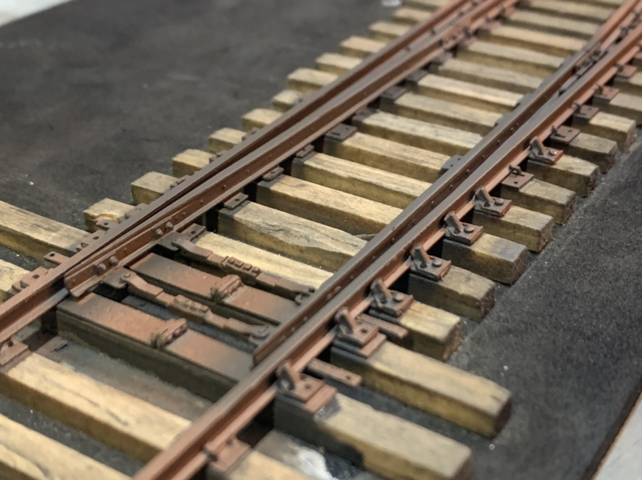
Once a sufficient number of ties were spiked to hold the rail, I removed the PCB ties soldered to the top of the rail. They were a little more difficult than I imagined they would be. I stripped all the paint from the area, coated them in flux and sweated them for several minutes at 890* while pulling at them with pliers.
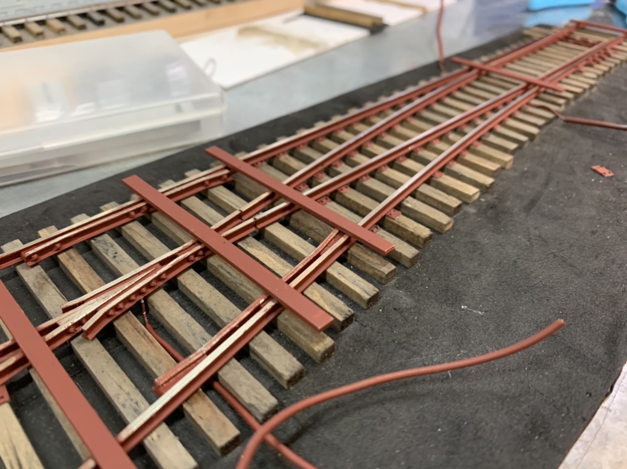
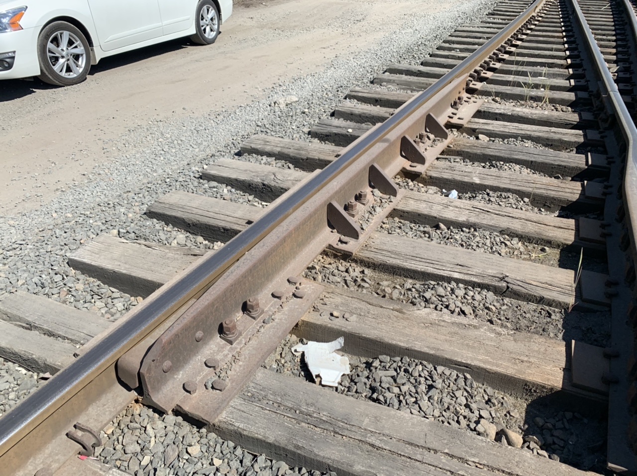
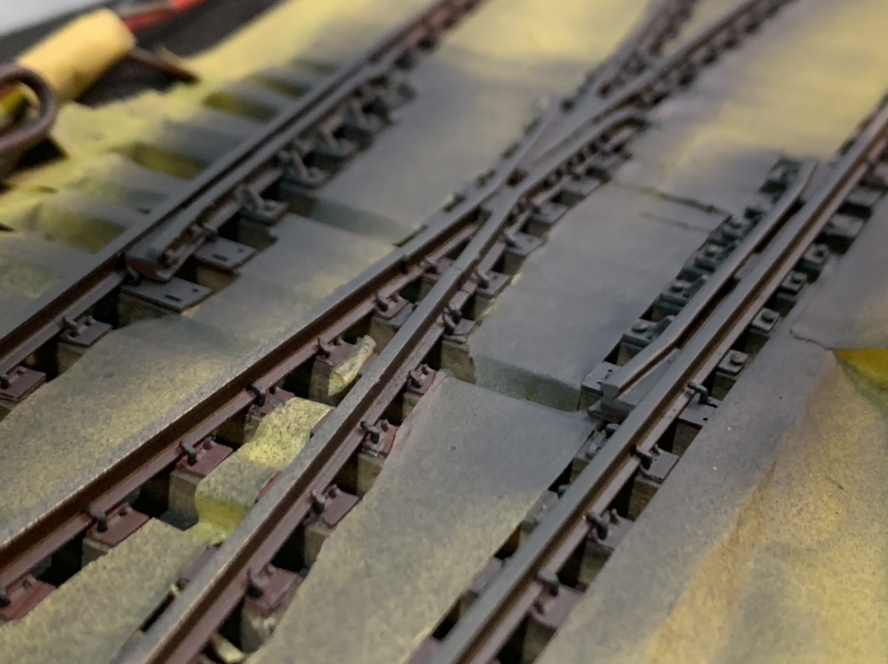
Because every prototype turnout I’ve ever seen has some kind of bracing for the guard rails. I decided to use some rail brace castings as guard rail braces.
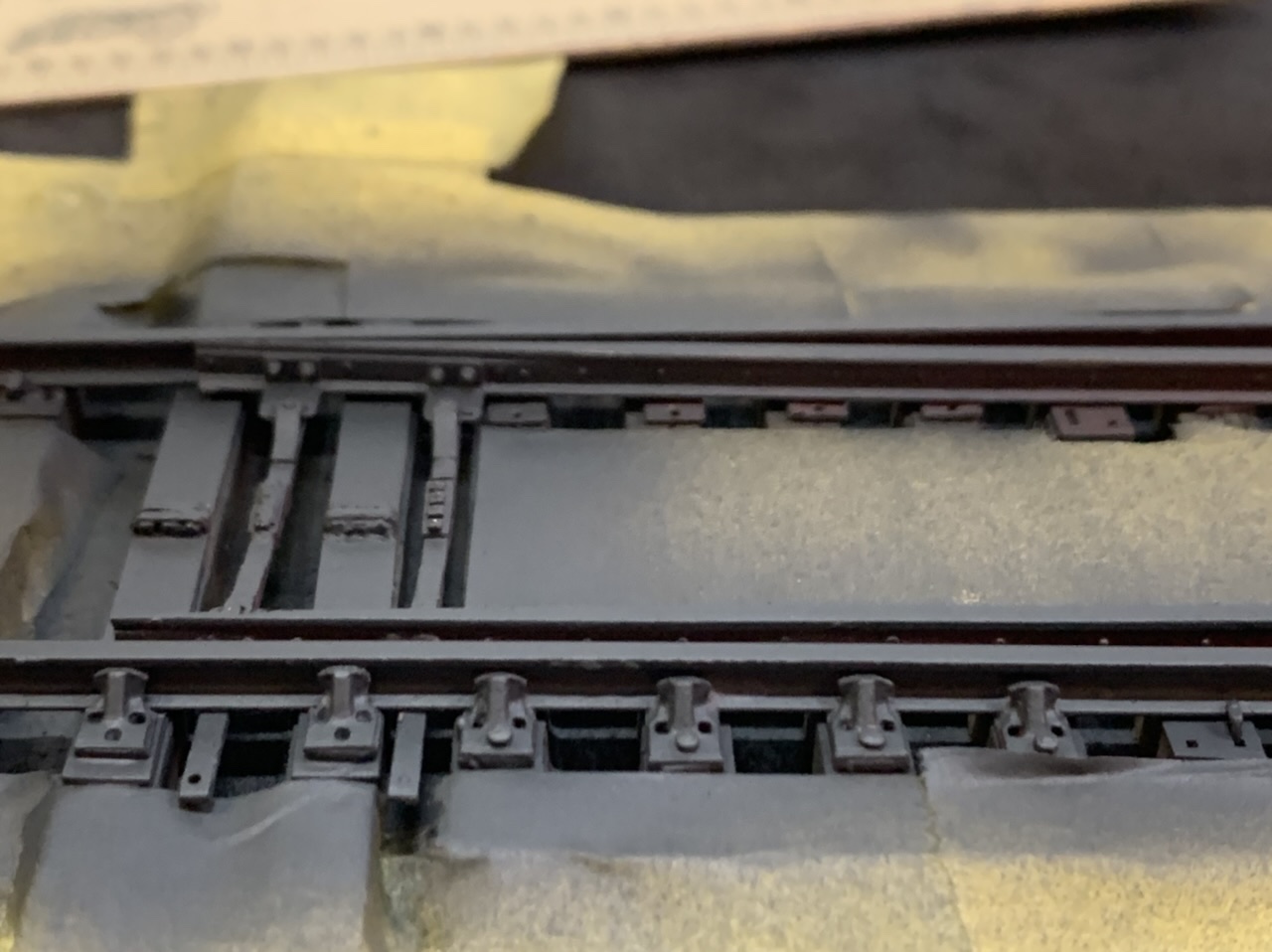
Despite trying to separate the finishing process I found I made enough changes to require repainting the rails so I masked the ties and hit the rails with Vallejo 70.603 German Panzer Grey primer. It was dead flat. This will be my go-to from now on, I’ll skip the Rus-oleum rattle can as it didn’t adhere well and left a glossy finish.
Lessons Learned
- Do not use EPS foam sub-roadbed!
- Spiking is a disaster. Ties collapse and spikes do not hold.
- I will seek a rigid product (I’m thinking either plywood or gator board)
- Templates are great!
- This build essentially used two templates. Most obviously the tie placement template this was definitely $40 well spent. Secondly was the turnout skeleton itself being able to be used as a tie plate template. This saved me countless hours in not having to fiddle with every single tie plate as I spiked the turnout.
- Spikes Spikes Spikes
- The spike problem hasn’t changed since the last time I spiked track (5 years ago)
- Walthers/Shinohara are the best fit with ROW tie plates, but no longer produced
- p87 are the best spike available overall, but the shanks are too narrow for ROW tie plates.
- Solder what you can.
- This is an awesome solution to incorporating the brilliant brass cast rail braces and gauge plates.
- I’ve ordered several samples of brass tie plates and joint bars from O-Scale turnouts to see where else this avenue can take me.
- Paint with Vallejo
- I thought that rattle can primer would be the way to go, but the Rust-oleum primer I used was not exactly super adherent to the metal rails.
- I have purchased some of Jim Lincoln’s 3D printed tie plate productsJim Lincoln’s 3D printed tie plate products. I didn’t want to use them on this experimental turnout, but I’m really excited about the future possibilities.
Time Spent
I mentioned before that the initial sub-roadbed cutting, tie laying and tie staining took 1 hour! I spent about one hour laying tie plates. Spiking and adjusting tie plates took about 6 hours. Masking the ties and painting the rails took about 1 hours. Essentially I built a fully detailed and functioning turnout in a week. Not bad at all, considering I’ve spent well over a hundred hours on my previous P48 turnout, which is still incomplete.
The Results
Next Steps
I was planning to ballast this turnout and add a working switch stand. It turns out the ballast I found is super ferrous, I spent hours sifting it this week and when I run magnets through its crazy how much material sticks to the magnets. I think I’ll have to find another source. I purchased the Right-O-Way Operating Raycor Switch Stand. Maybe my project for next week.
Especially
Thank you Jay Criswell for continuing on with Right-O-Way. Lou Cross should be proud. You are a top notch person to work with, just as Lou was.
5,969
Hello, I am Herbert from Czech republic actually building scale 0 layout after Southern Pacific prototype. I planned to use Atlas turnouts, but after I have seen this very nice handlaid turnout, I would like to use them. Unfortunately, I am not keen in building kits. So my question is, if there is somebody who can build and paint 4 turnouts in the scale 0 from RightOWay or Scale 0 Turnout kits for me. 2x #6, 2x #8, code 125. I pay in advance, I am aware of the building and painting costs and I am not in hurry, delivery at the end of 2022 would be OK. Any advice would be very appreciated. Thank you Herbert
Great looking! I’ve had good luck with Micro Engineering micro spikes but you do have to trim the heads on some of them. Jim Lincoln’s hook plates work great too. I use working high stand switches from Miniatures by Eric, and replace the brass handle with a steel one for durability.
Thank you Jamie. I’m not very fond of Micro Engineering spikes, but it seems to be the default option. I’m pretty impressed by the switch stands Right-O-Way sells, but I’ll have to check into the Miniatures By Eric switch stands.
That really turned out nice.
Thank you Chris!
Very well done Greg!
Thank you Shawn. Seeing your work is really inspiring for me.