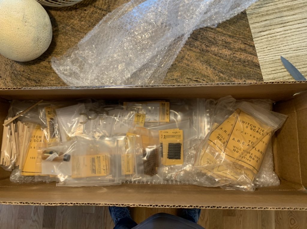
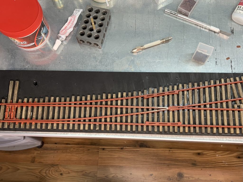
In 2022 I was commissioned to build a number of O scale track components for another modeler. The total project encompassed 4 turnouts, 2 custom designed diverging track sections, 2 custom designed bridge track sections and several turnout switch stands. This is a diary of the progress on that project.
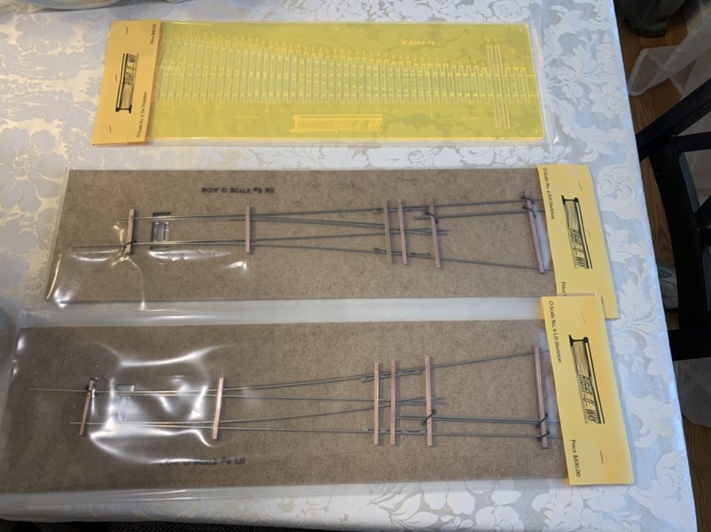
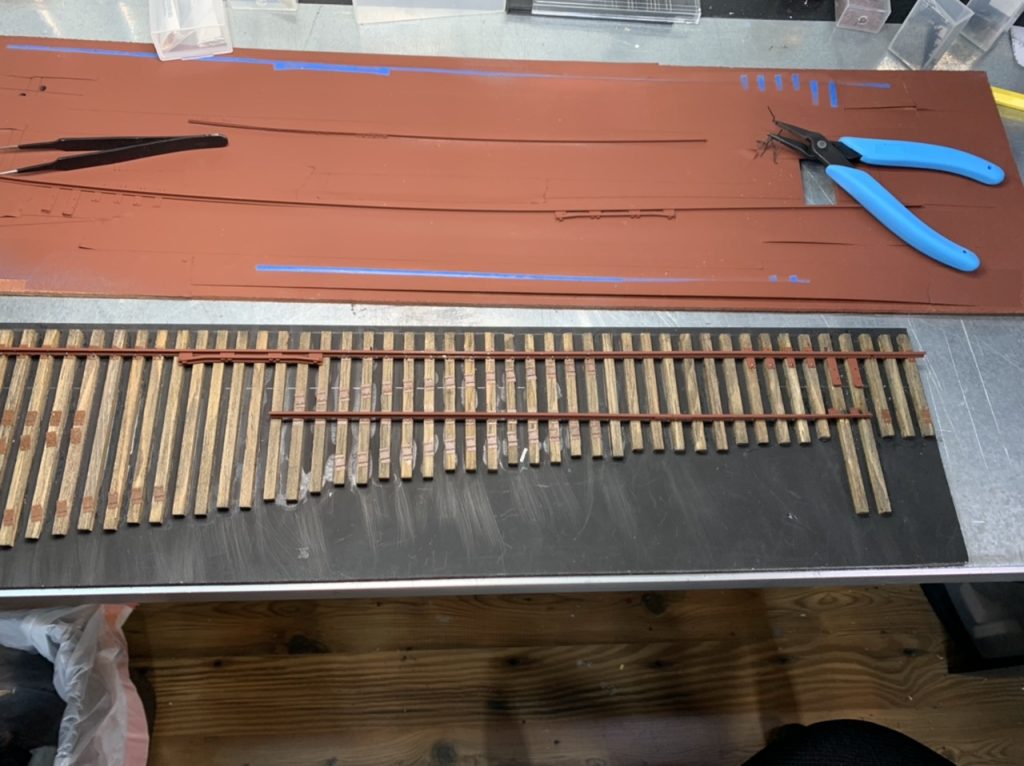
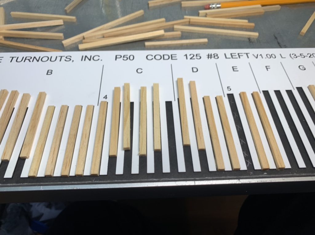
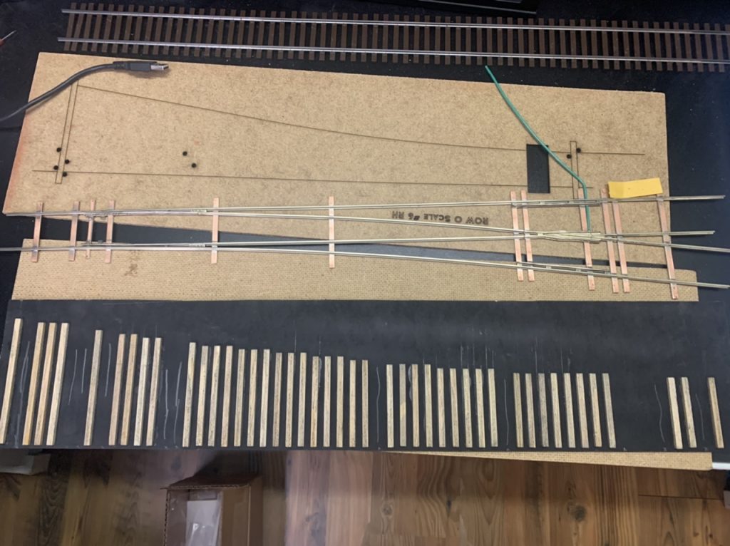
I’ve been commissioned to build 4 O scale turnouts (#6 Left, #6 Right, #8 Left, #8 Right). The turnouts are mounted on gator board. The component parts are being delivered from right-o-way.us and oacaleturnouts.com. The goal is to build realistic O scale turnouts as inspired by my previous Proto48 turnout build.
I will also be building several O scale switch stands.
May 17, 2022
May 18, 2022
May 19, 2022
May 20, 2022
May 21, 2022
May 22, 2022
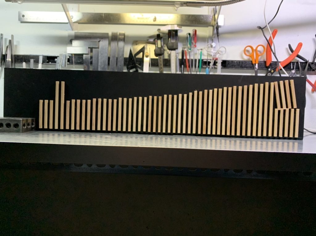
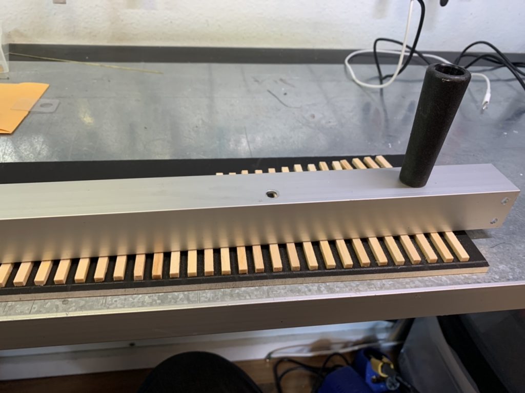
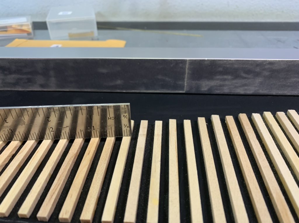
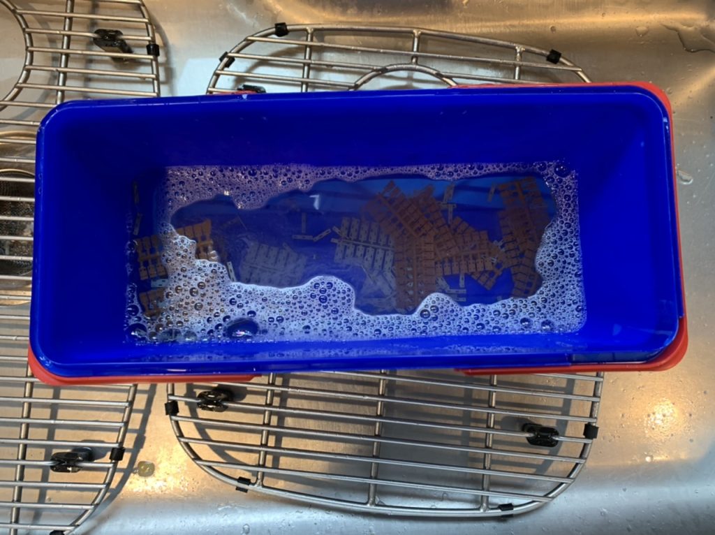
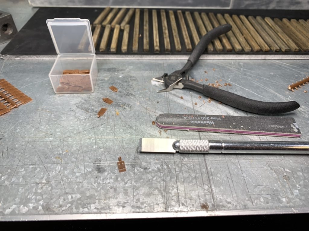
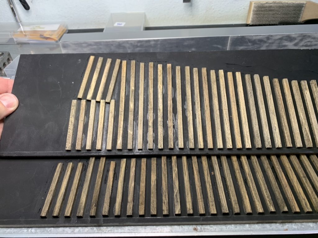
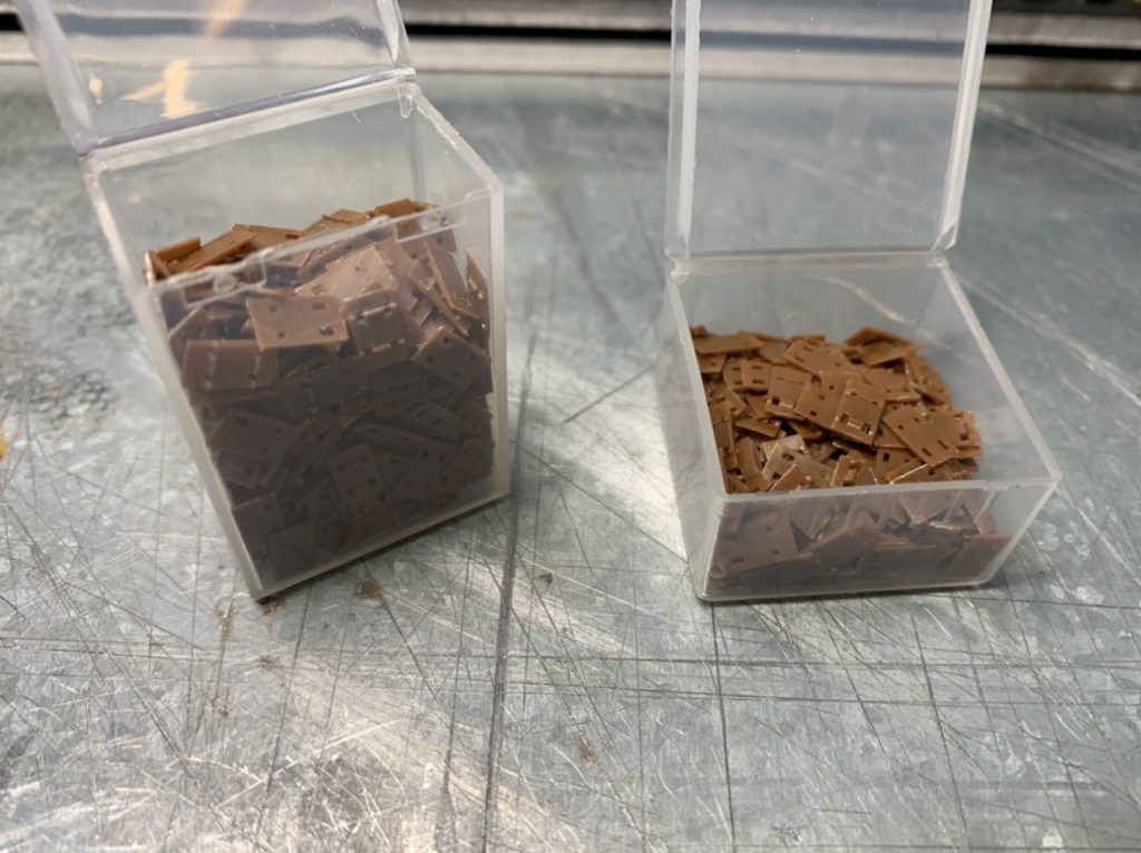
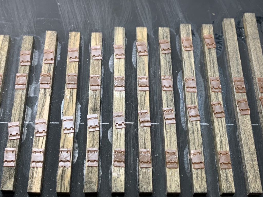
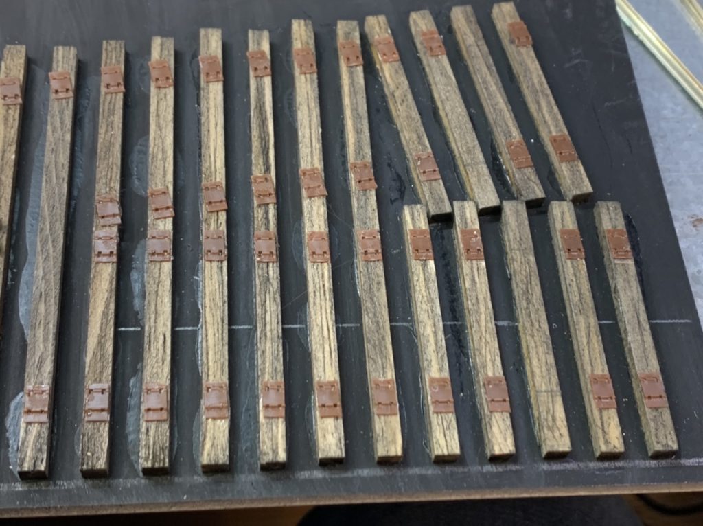
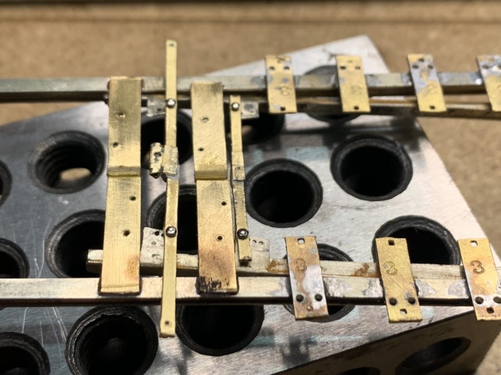
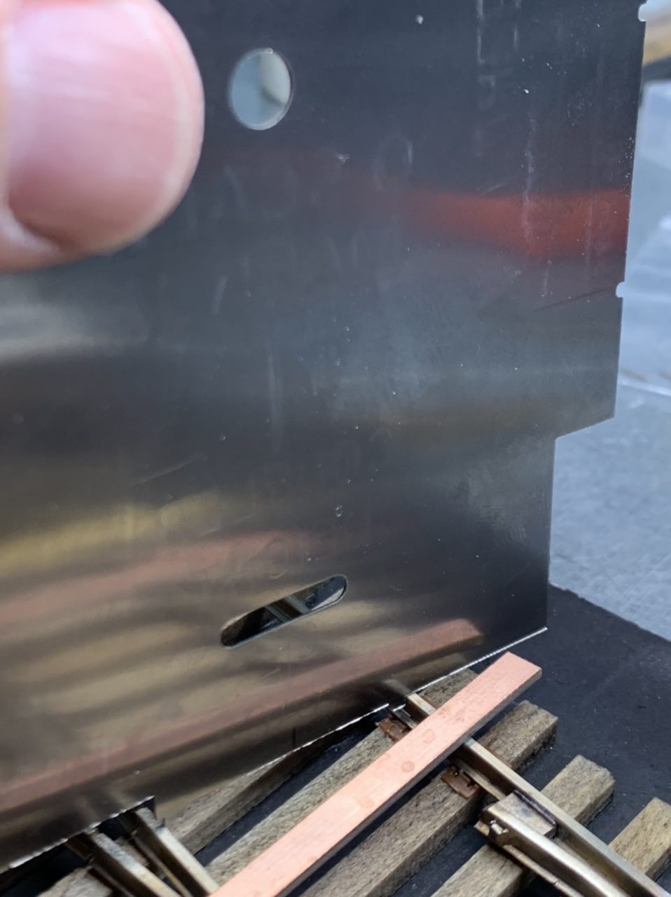
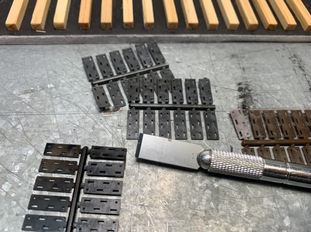
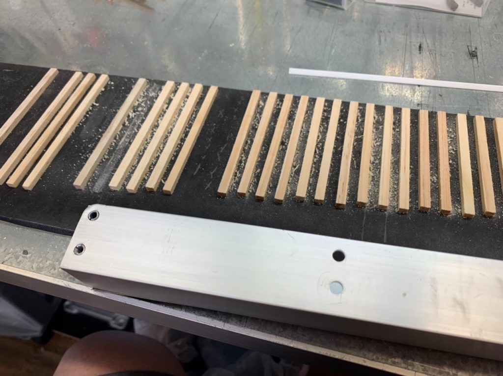
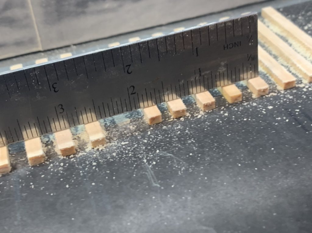
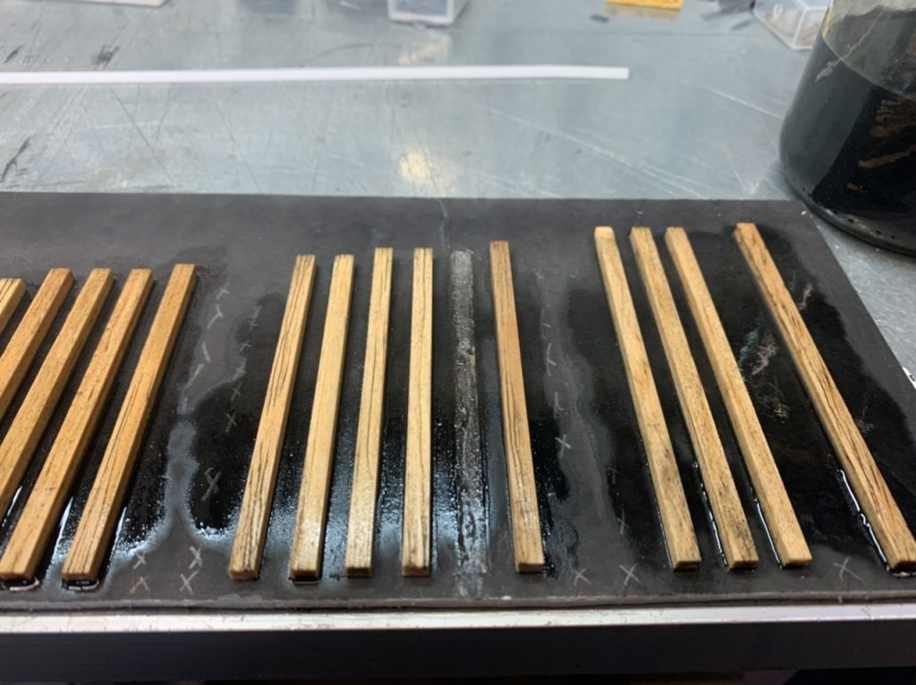
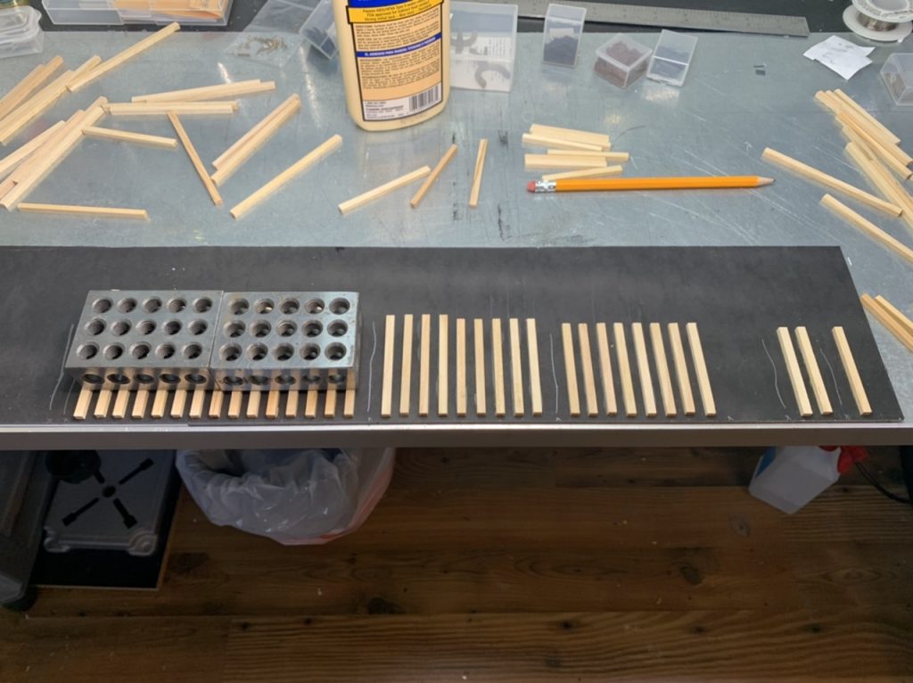
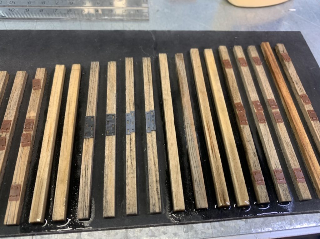
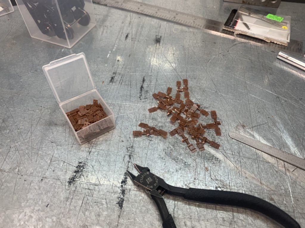
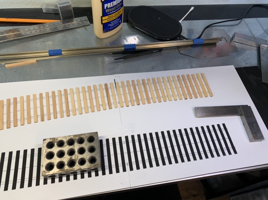
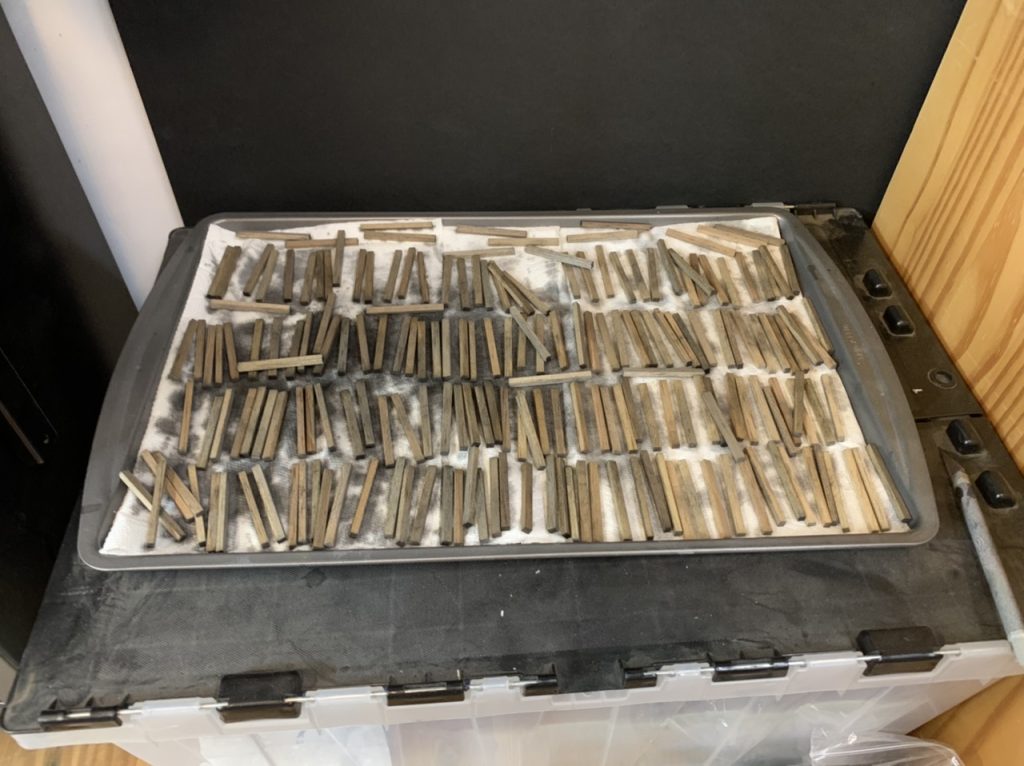
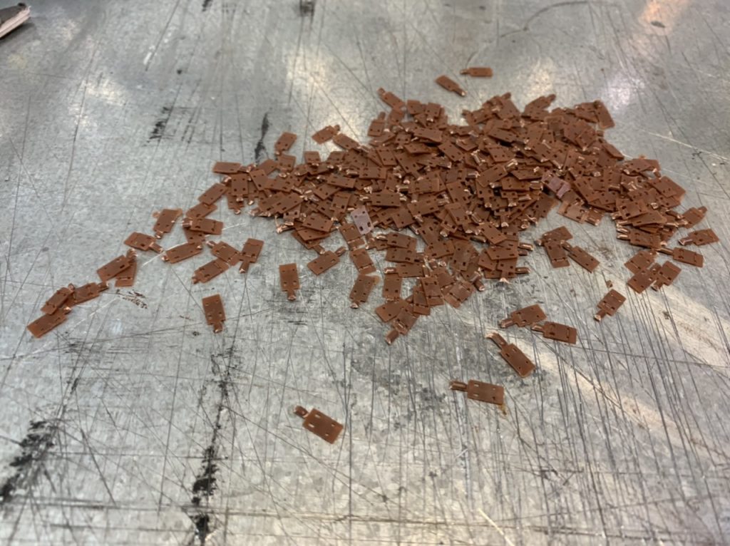
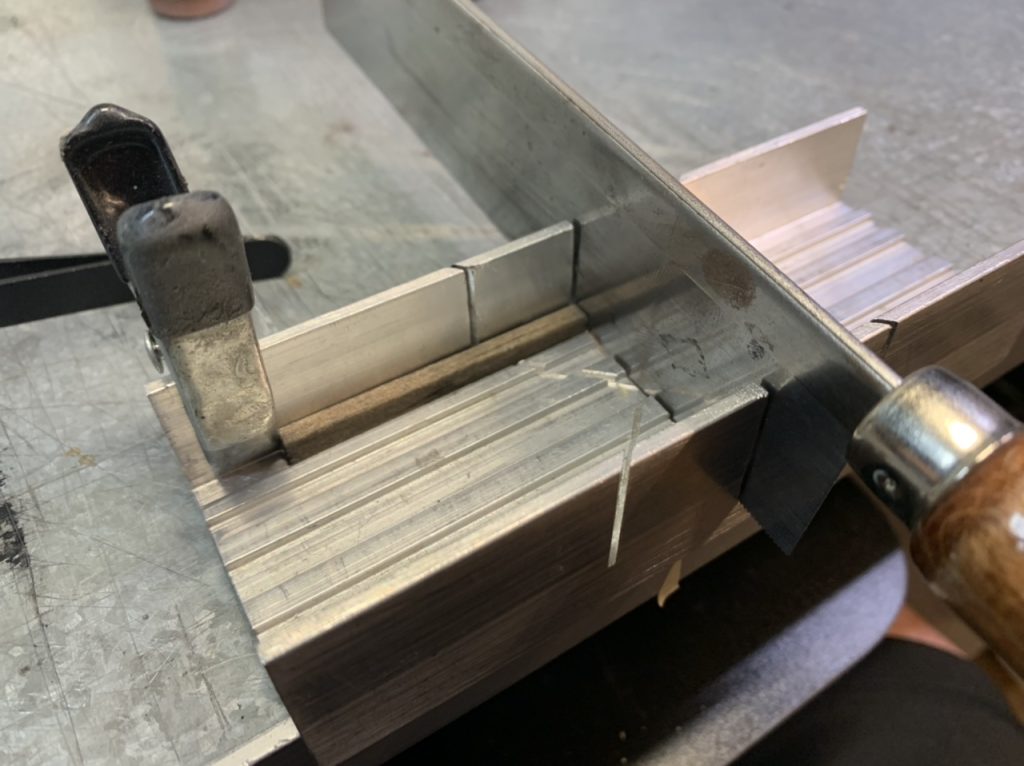
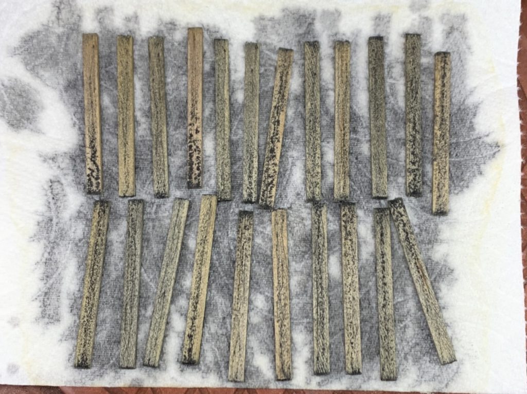
I continued to cut the first 200 tie plates today and washed the next set of 400.
May 23, 2022
May 30, 2022
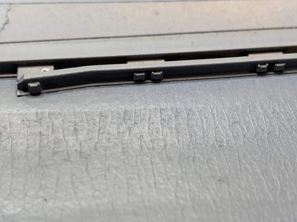
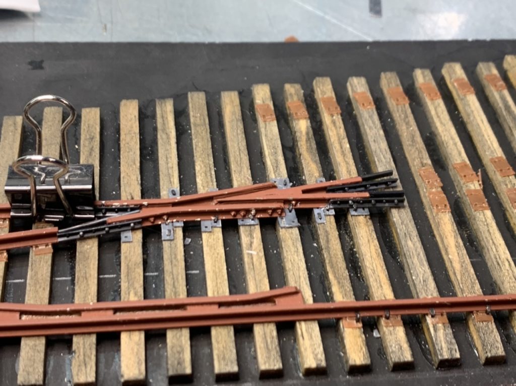
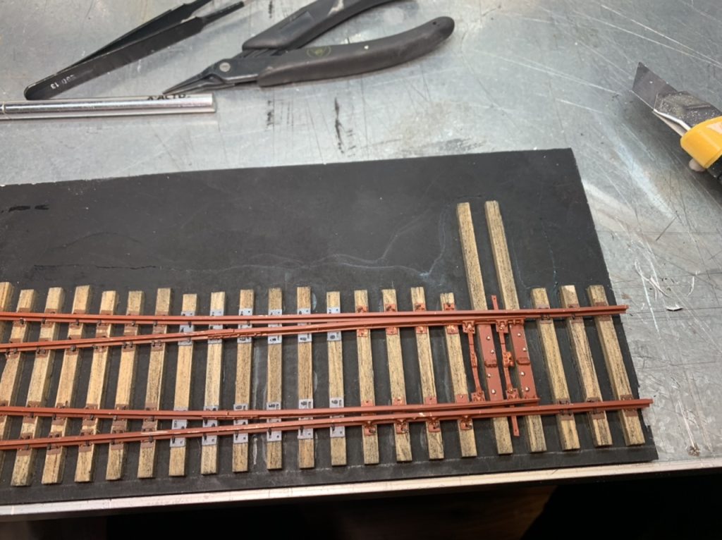
I installed rail braces to the #6 Left turnout today.
Today we discussed hand laying some connecting tracks from the diverging side of the #8 turnouts to the point side of the #6 turnout. This will be a future project, when I have the #8 turnouts in hand I can start to figure out the geometry required.
Today we discussed adding clevises and rods to the switch stands to have them ready to install. This is something I will investigate how to make it happen.
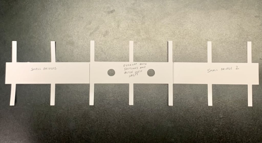
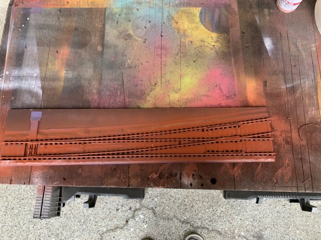
Today we discussed bridge tracks for 2 bridges. When we can get dimensions I think I will make a bridge deck mock-up to use as template for laying the bridge ties.
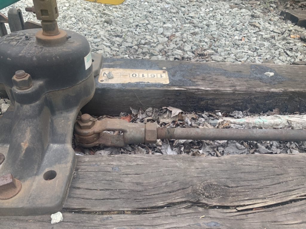
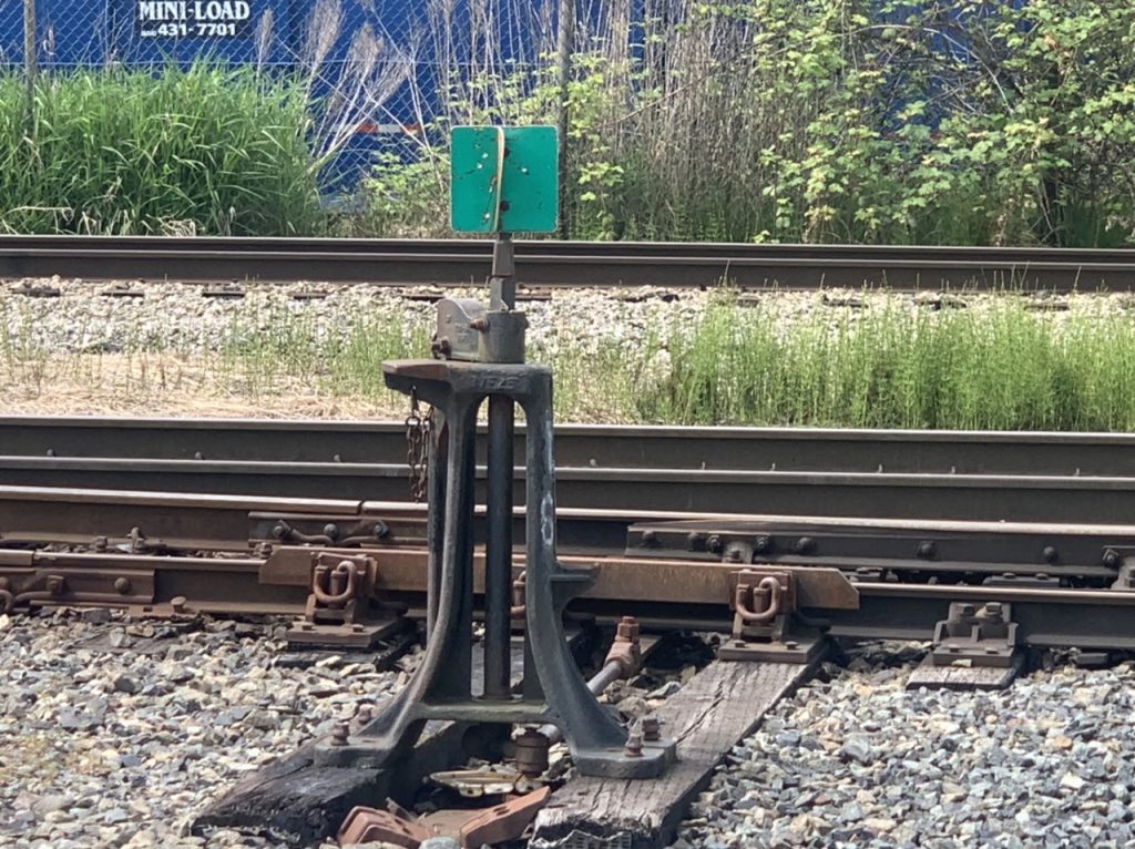
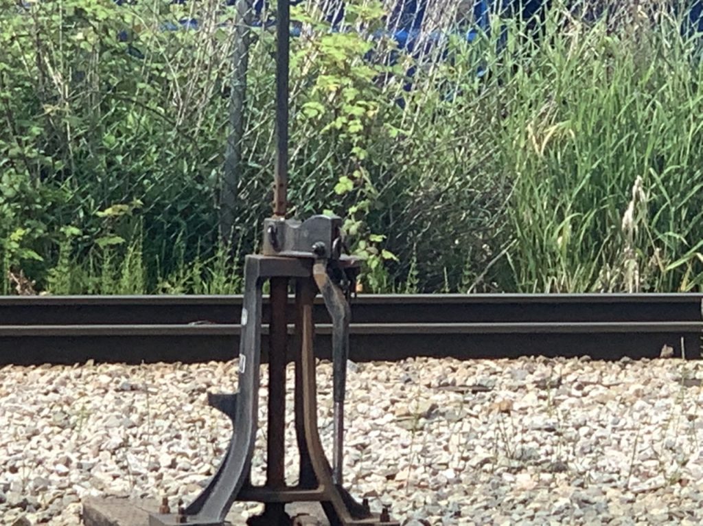
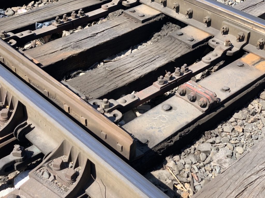
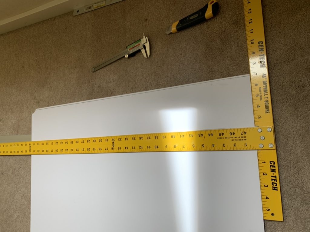
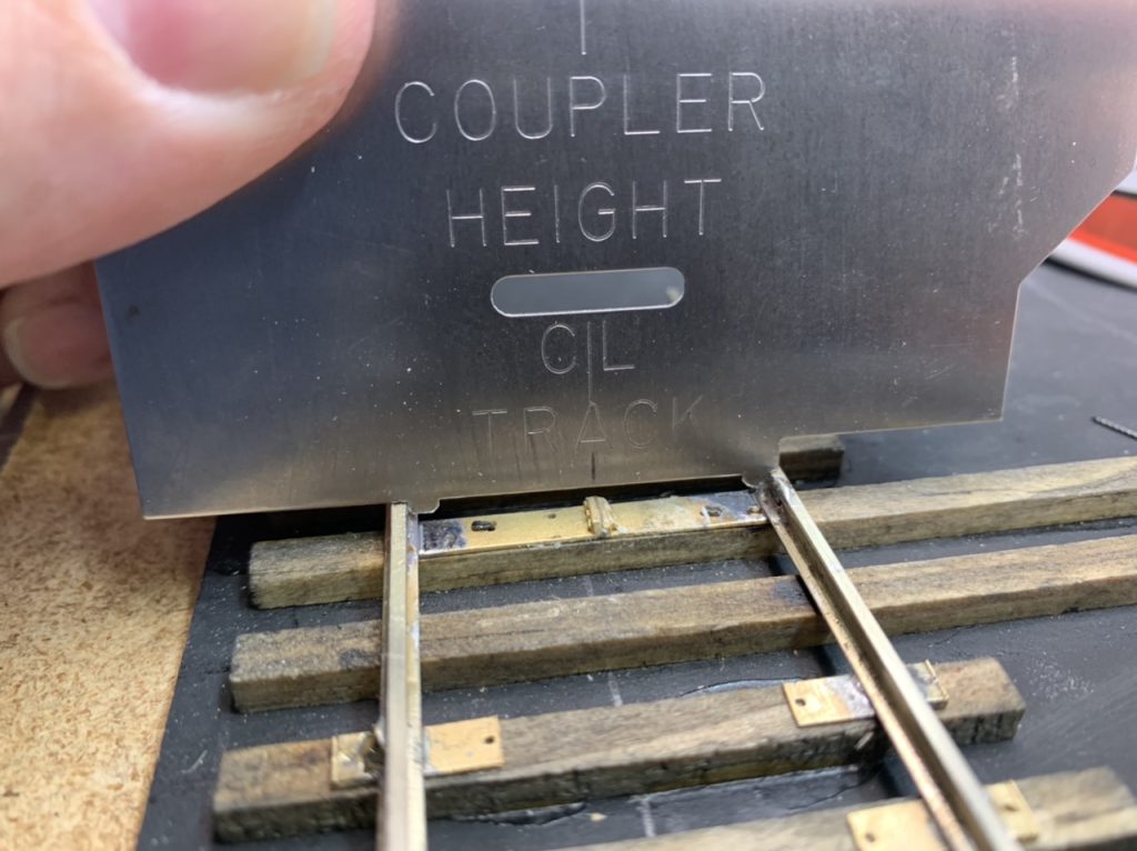
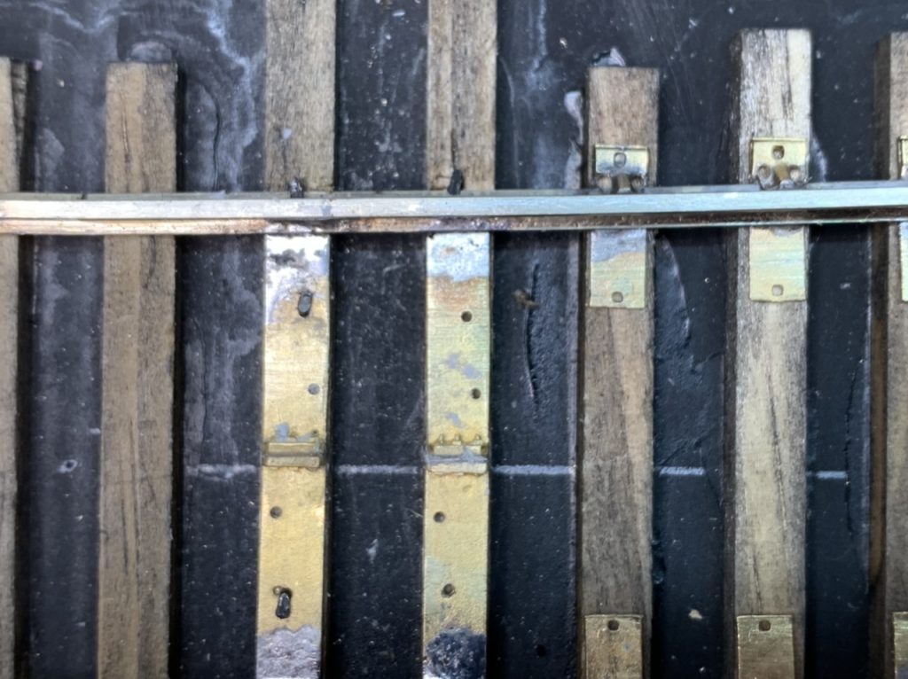
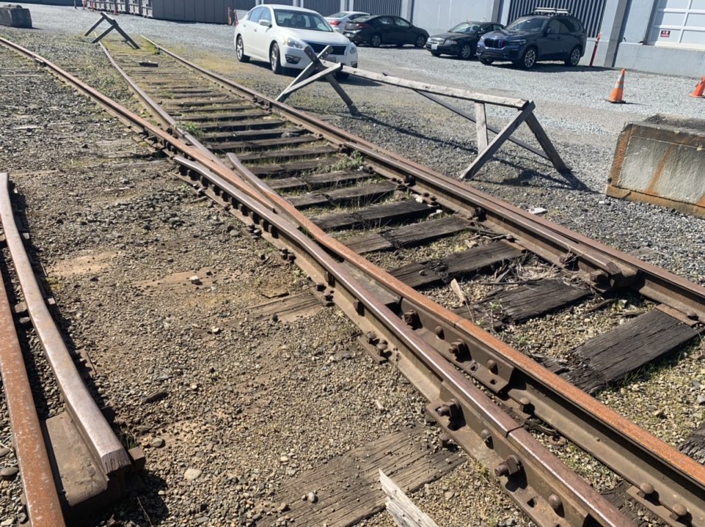
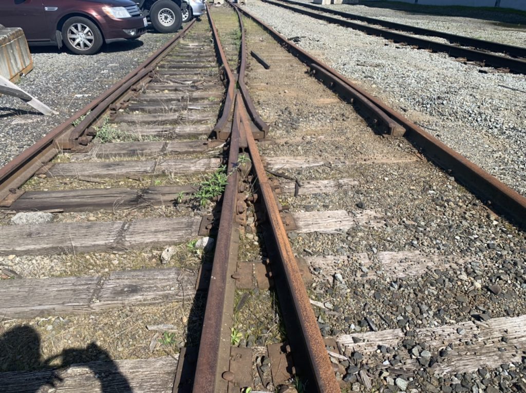
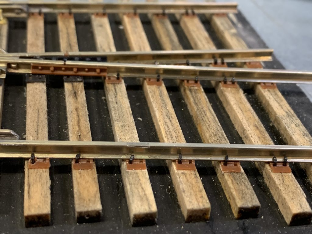
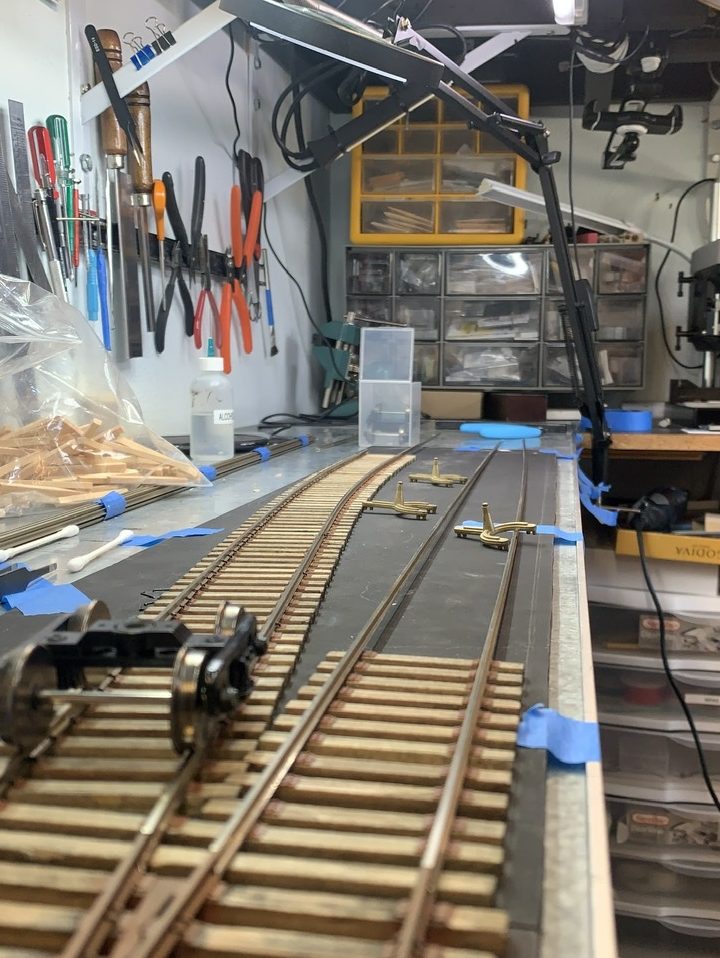
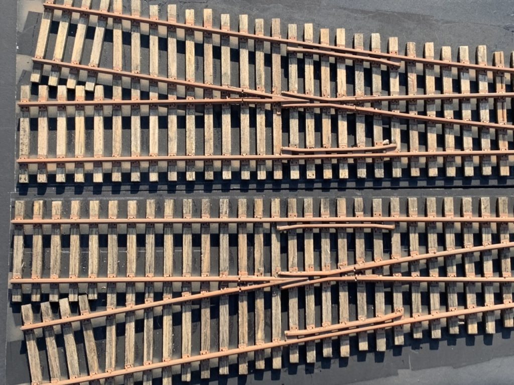
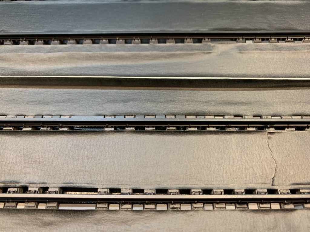
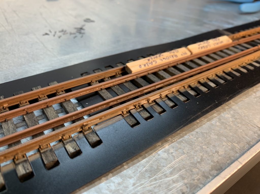
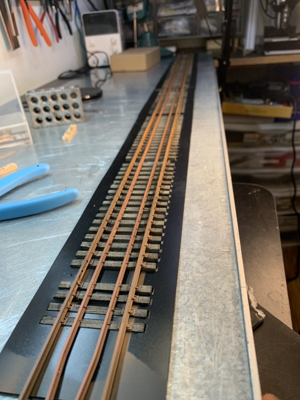
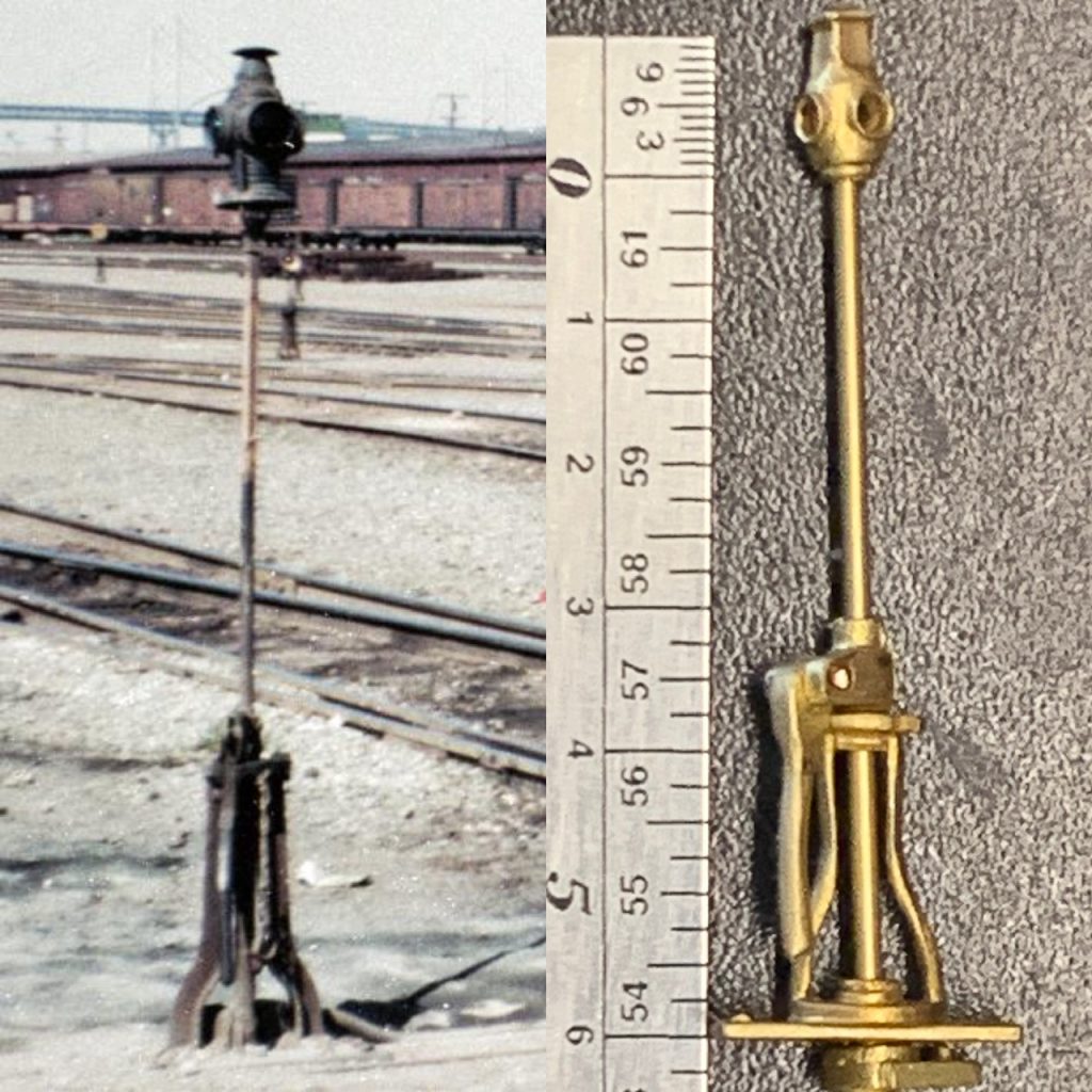
I recently took some reference photos to help with the project.
May 31, 2022
I continued to work on the # 6 Left turnout tonight.
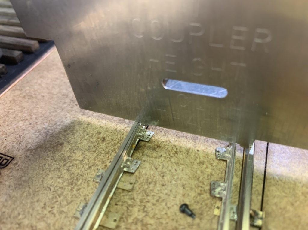
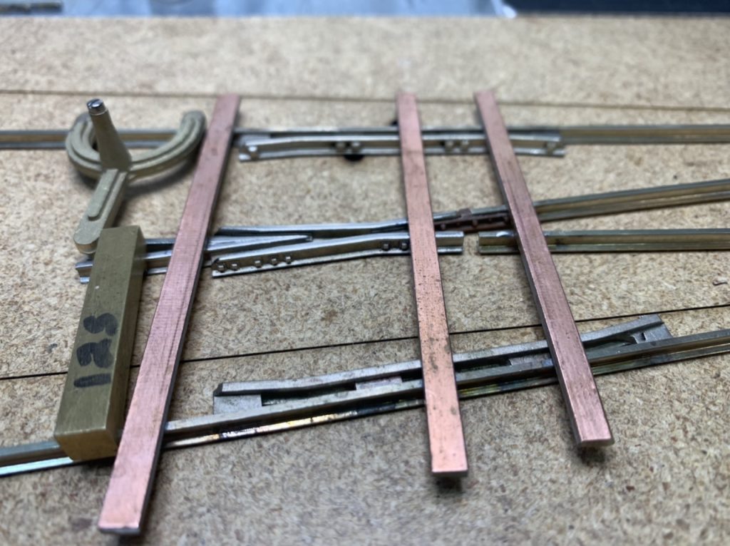
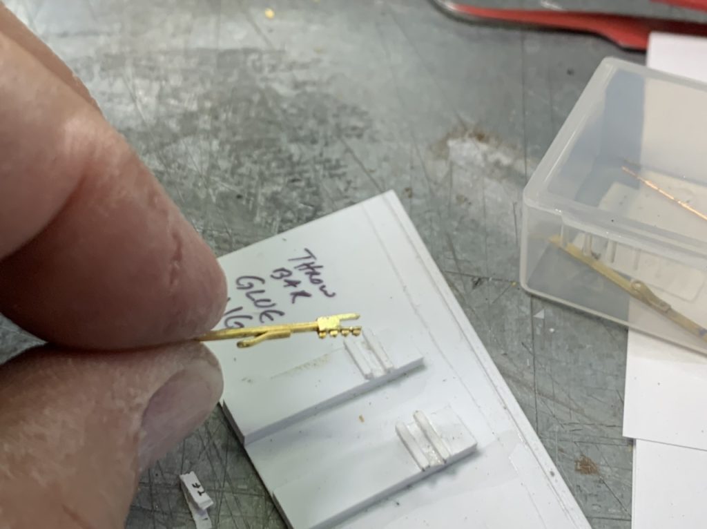
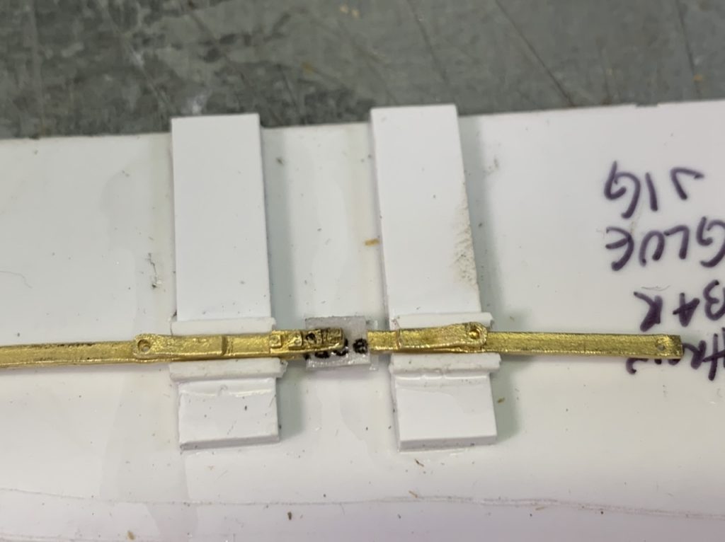
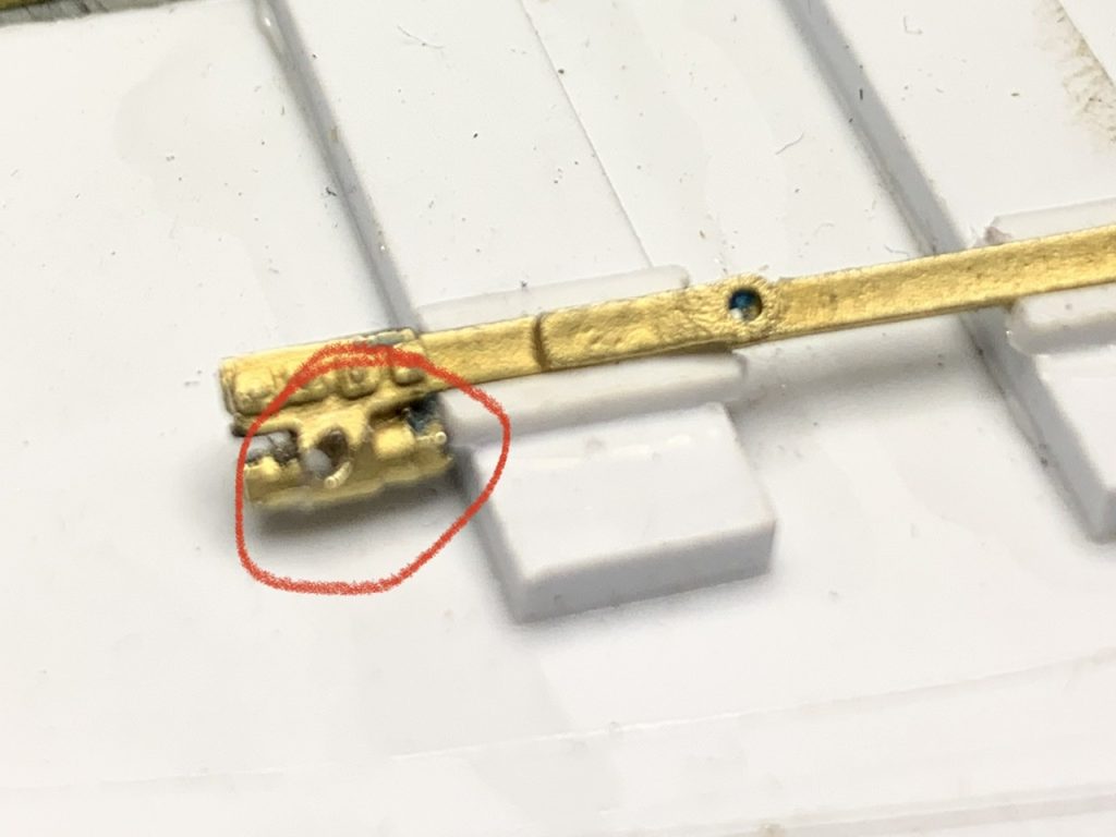
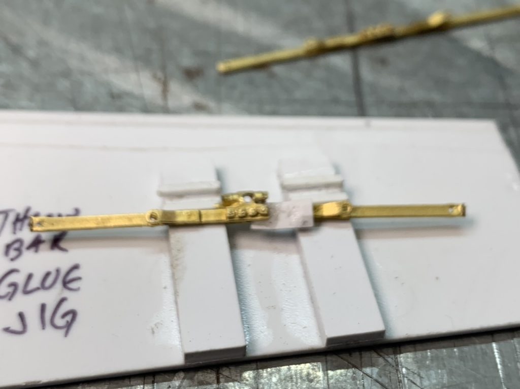
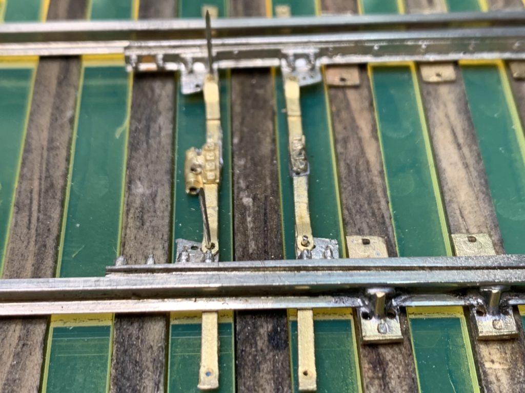
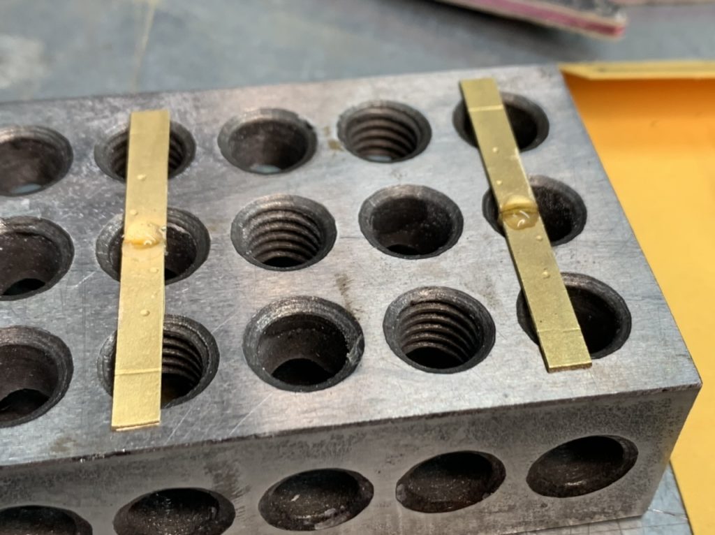
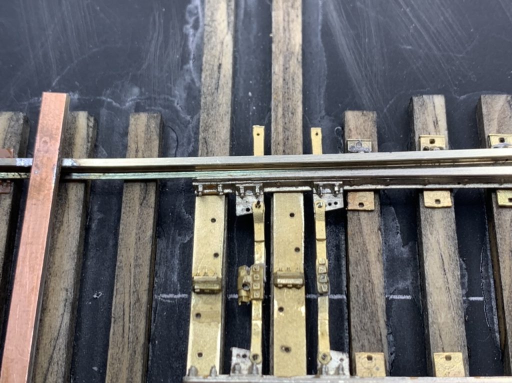
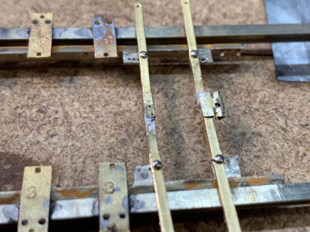
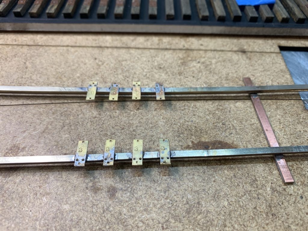
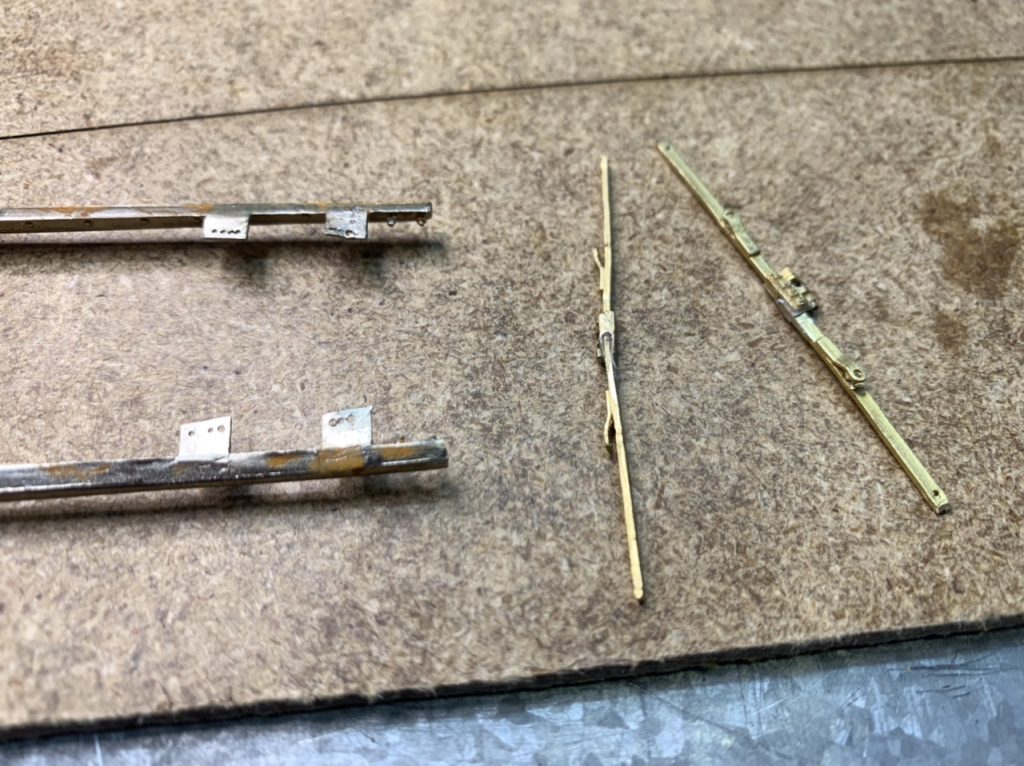
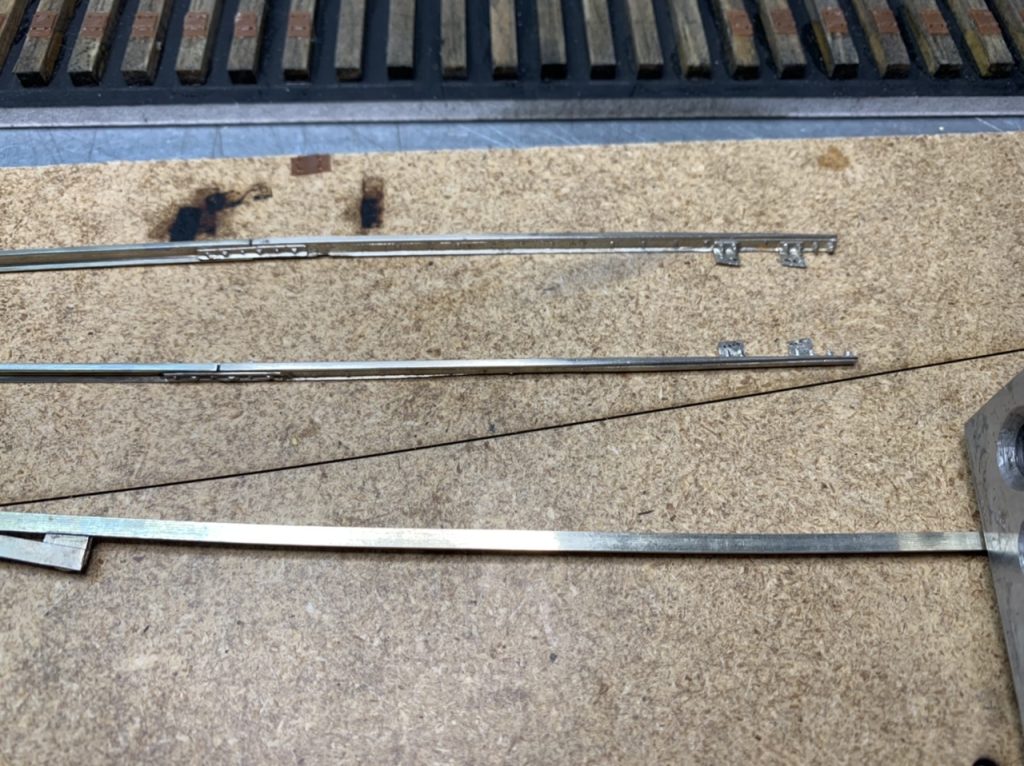
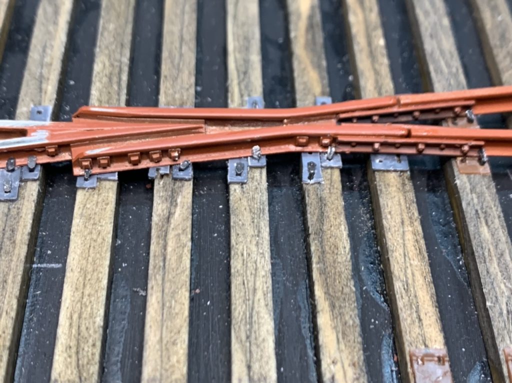
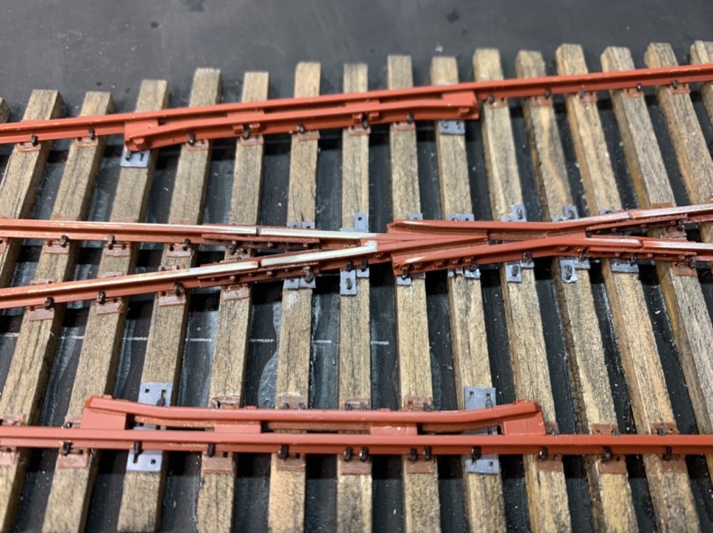
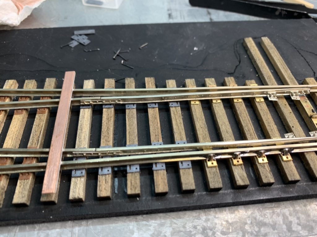
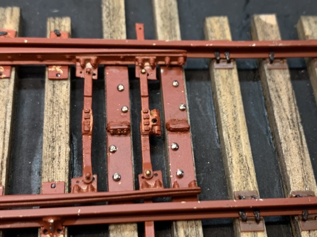
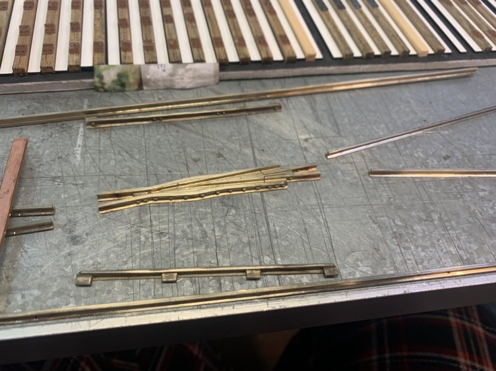
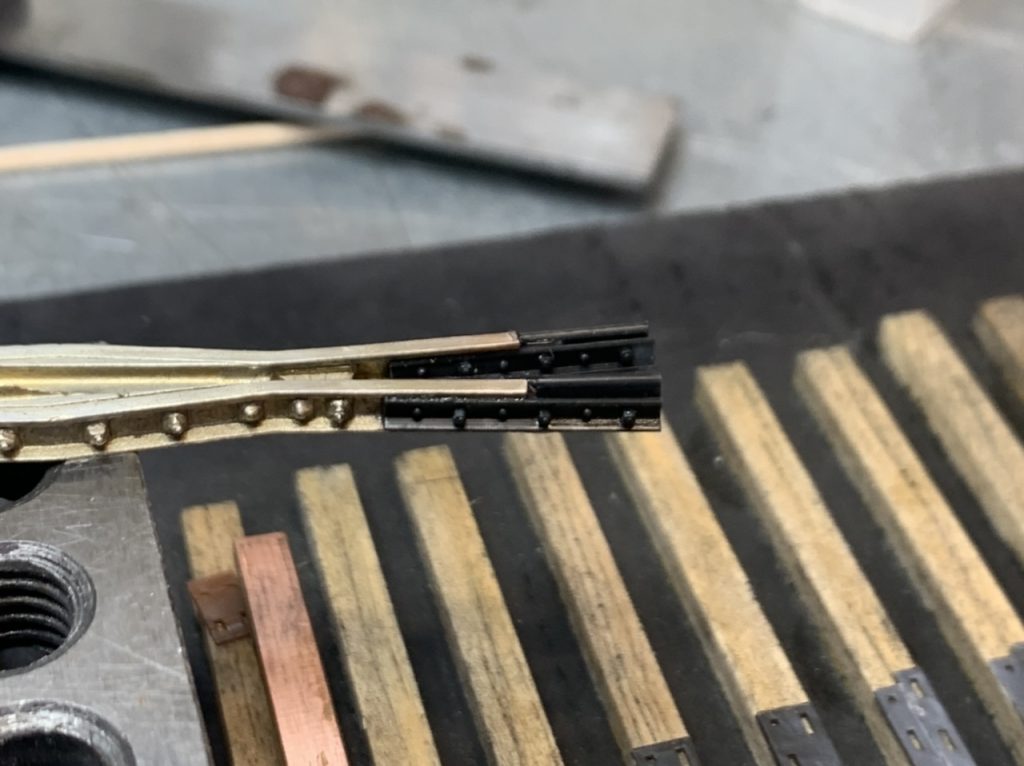
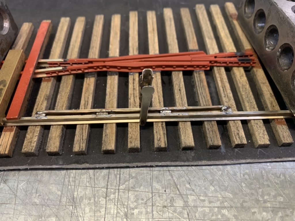
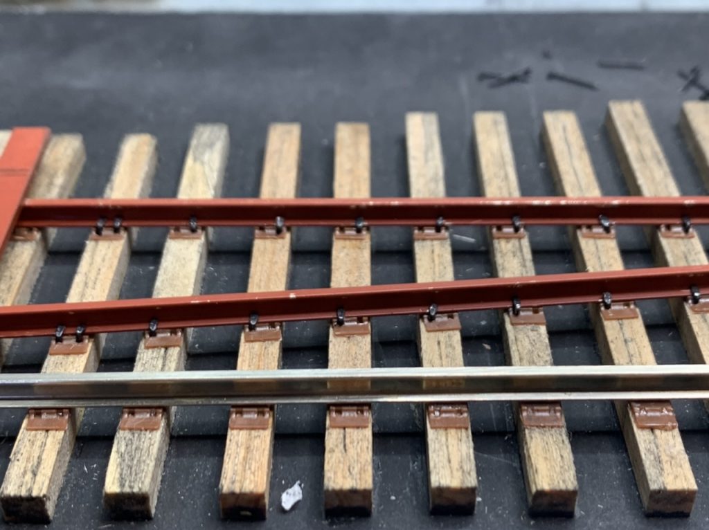
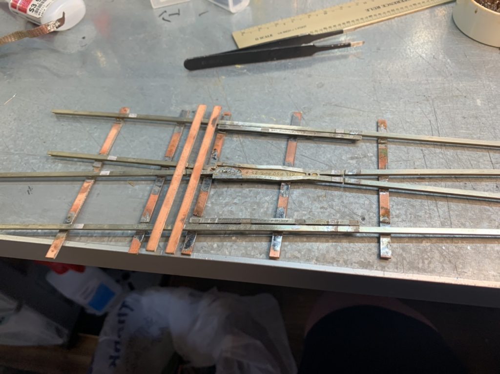
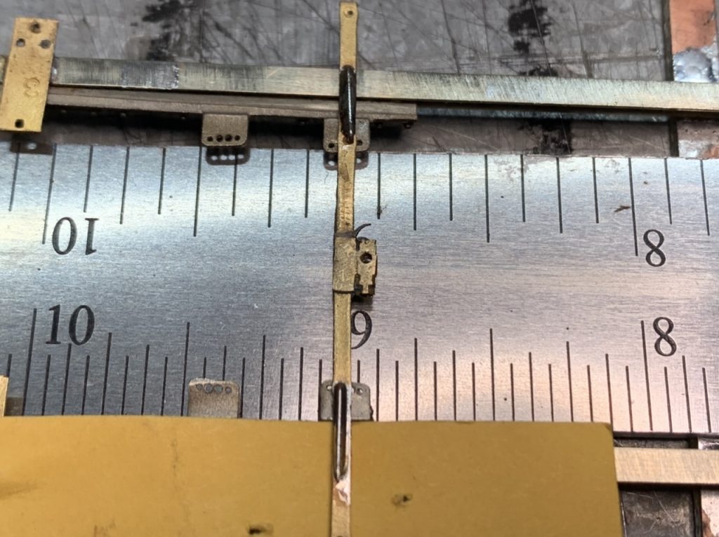
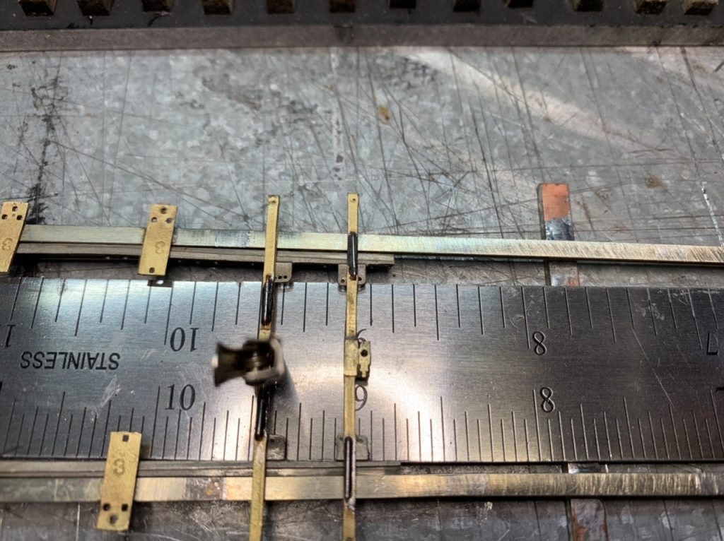
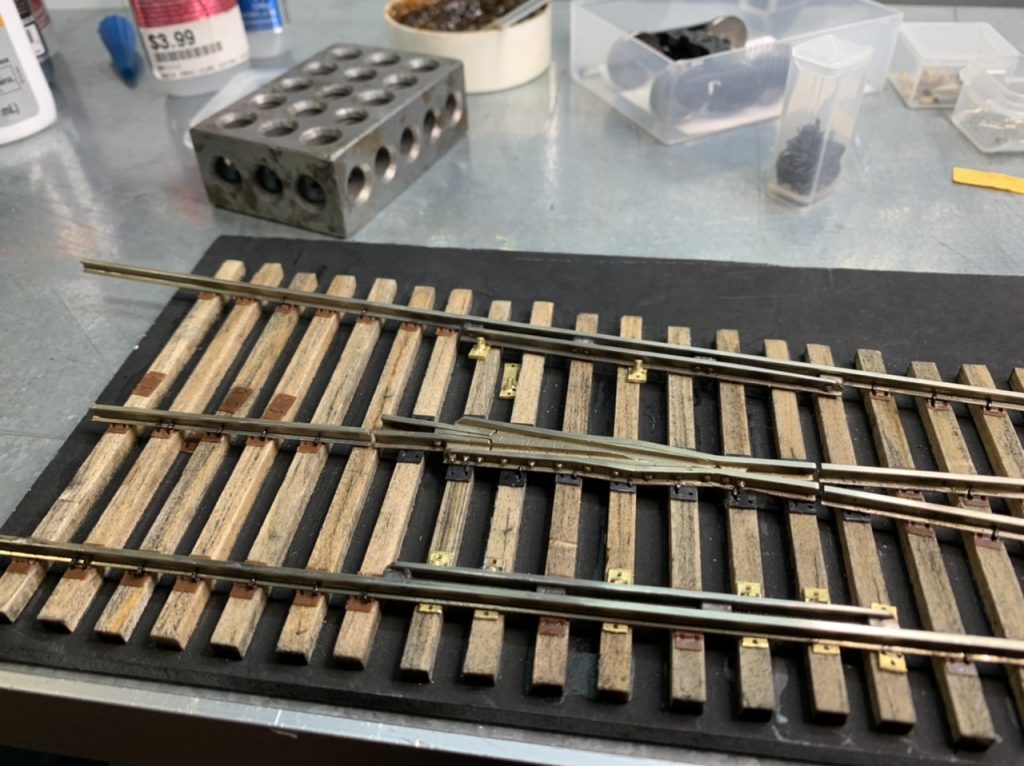
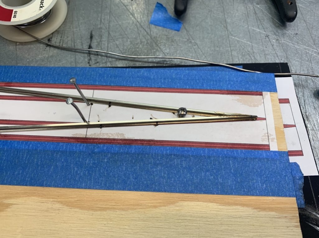
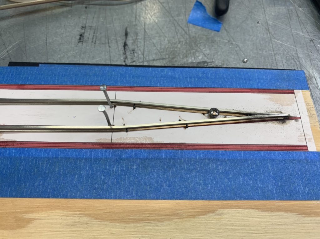
I removed the original short throw bars. I am test fitting the new throw bars, they are longer and will work just fine. They still need to be insulated, glued together and drilled for tortoise operation. I made a throw bar glue jig.
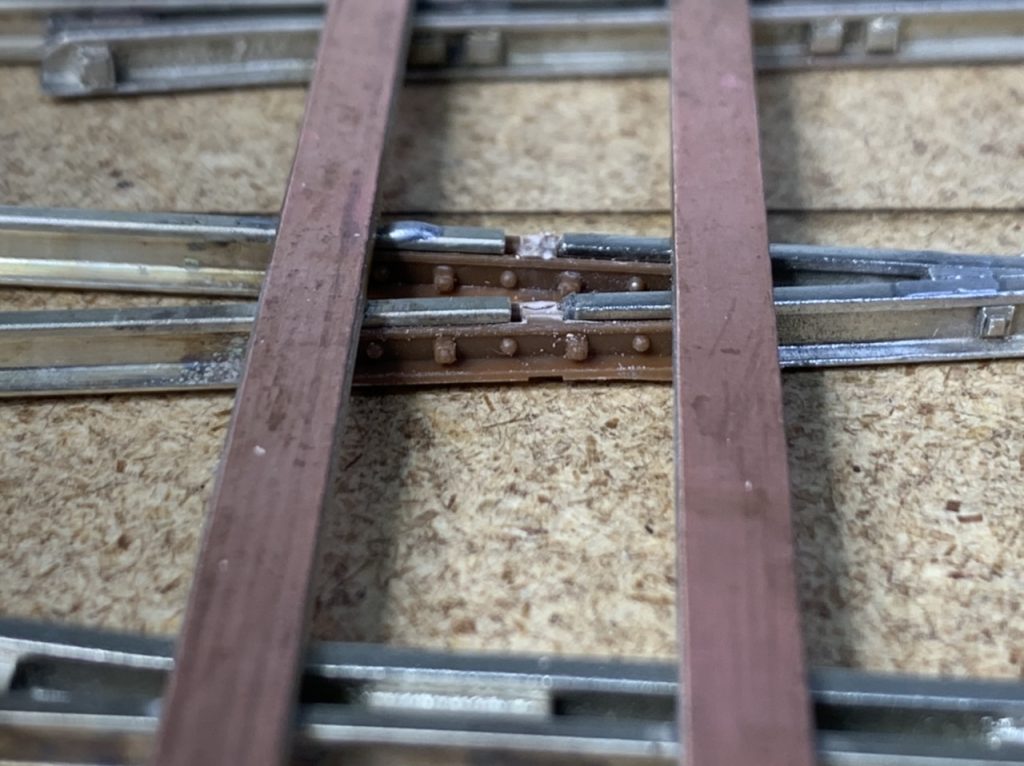
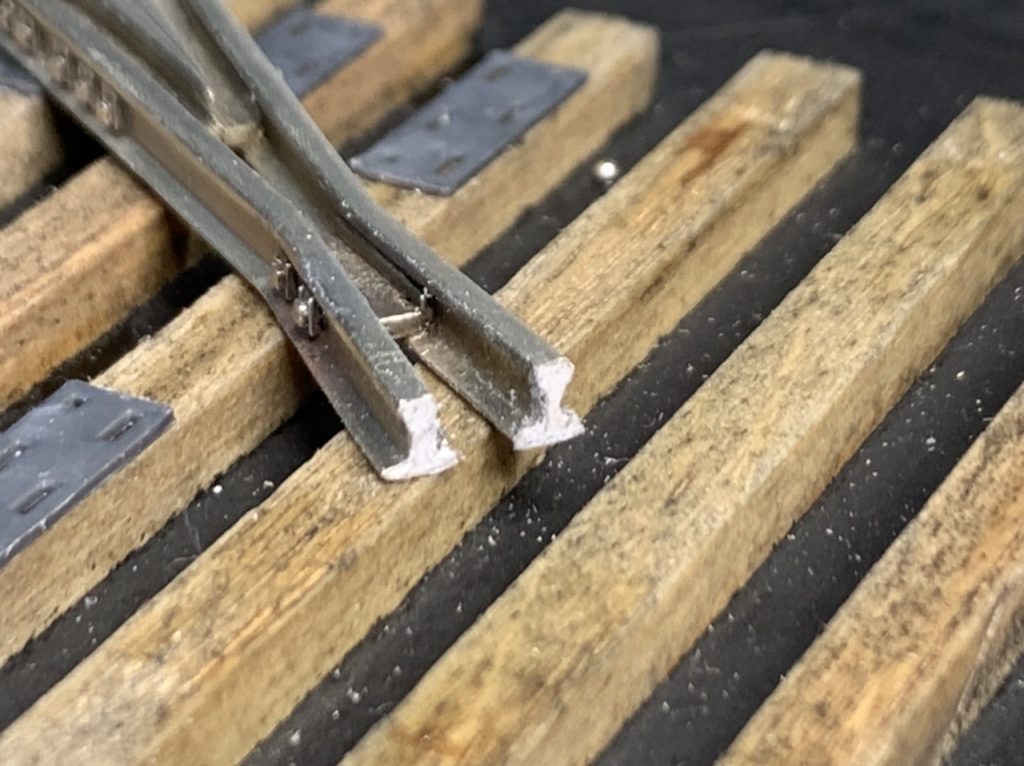
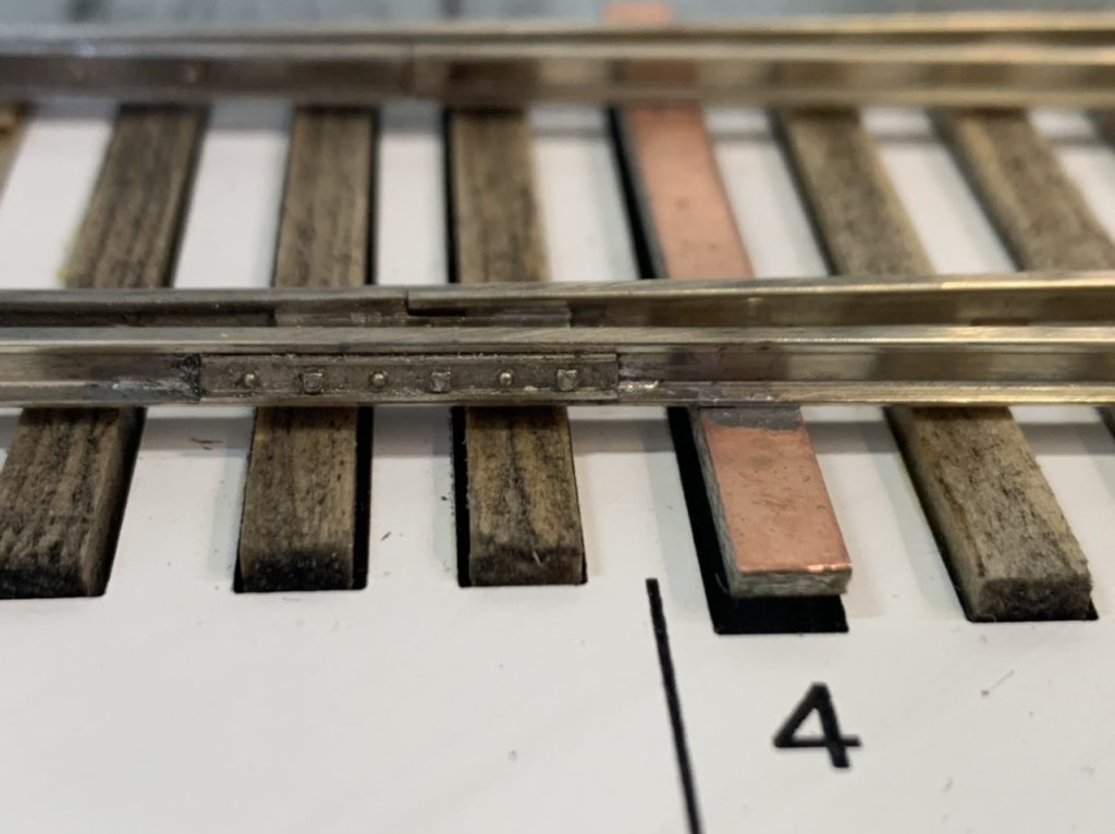
I desoldered many points on the turnout out kit to correct the gauge. I removed the frog because it was out of gauge and not insulated.
The frog should be insulated. The options to insulate the frog.
- Use the right-o-way insulated rail joiners. These are convenient, but leave a pretty large gap between the adjoining rails. Also, they have a tendency to deform. They fit ok on the rear of the frog, but not the point end.
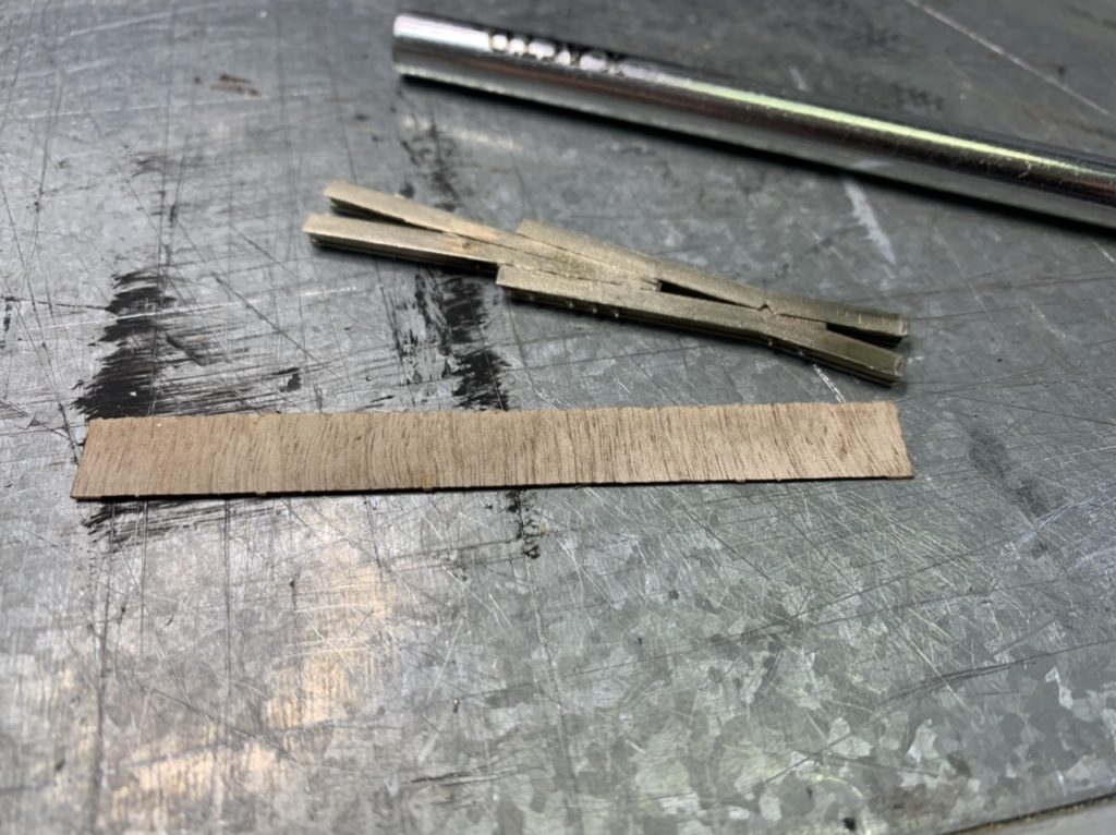
- Thin wood insulation with glue on plastic joint bars. Wood may be the best material to handle expansion of the track. I’m leaning toward this method.
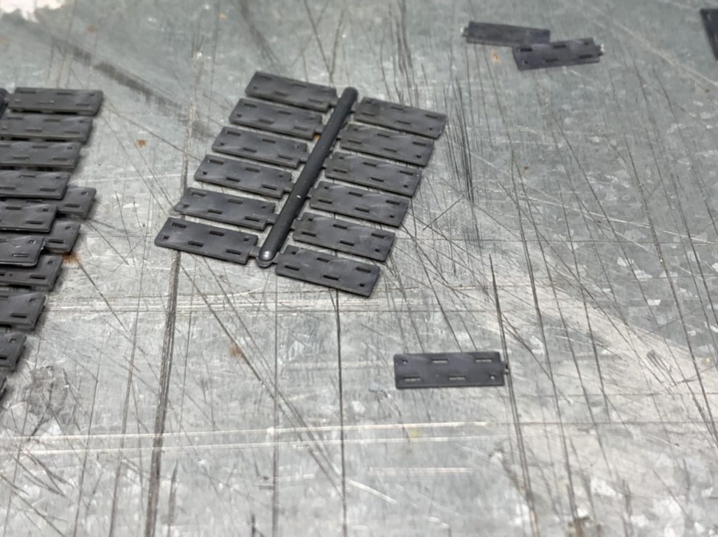
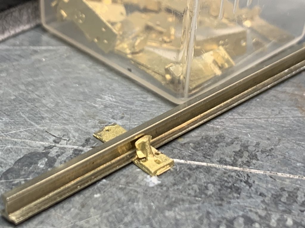
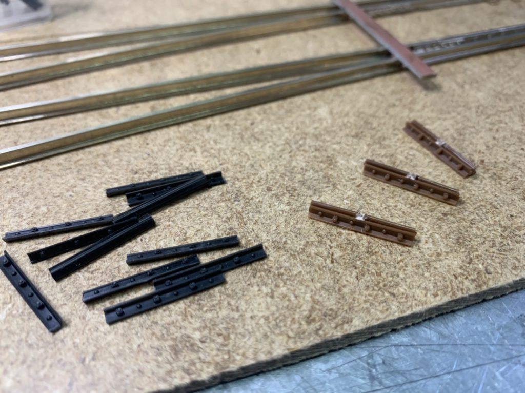
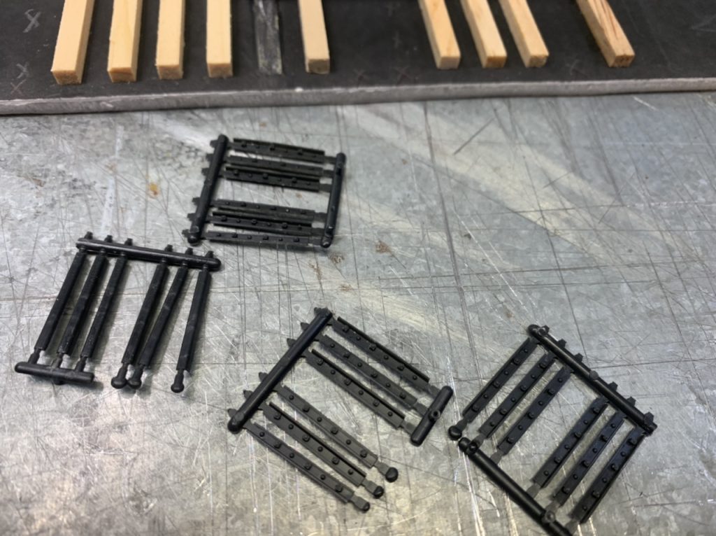
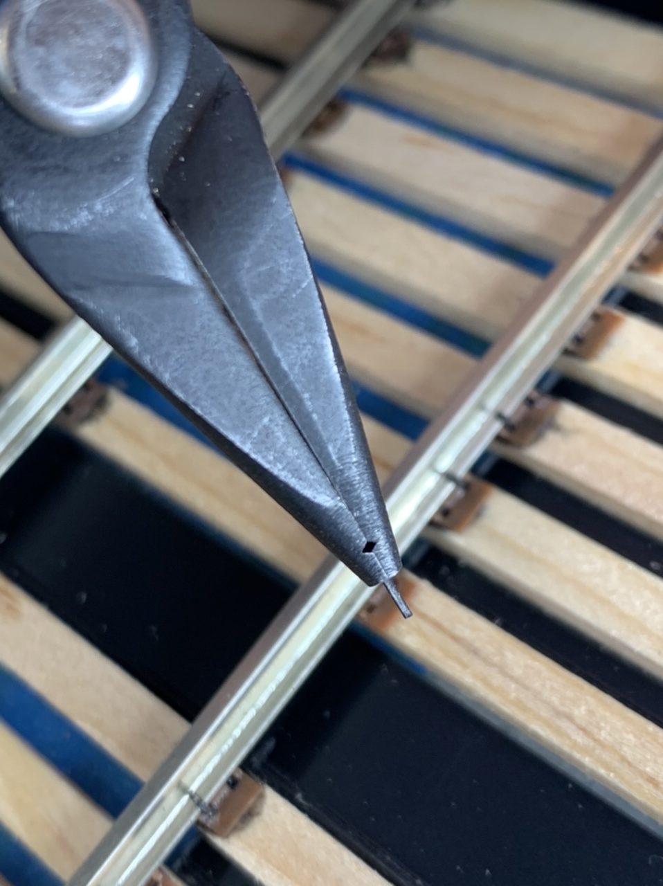
I also readied another 24 rail braces and cut the insulated joint bars from the spruces.
June 1, 2022
Today I continued to work on the throw bars and frog of the #6 Left turnout. Most of today was experimental to develop methods, this stage should go faster on subsequent turnouts. I also prepped another 12 rail braces.
The Throw Bars
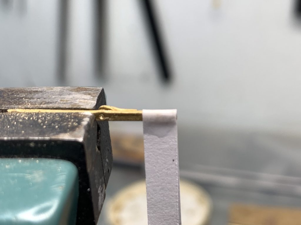
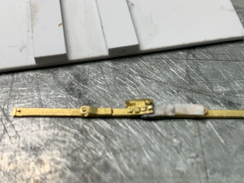
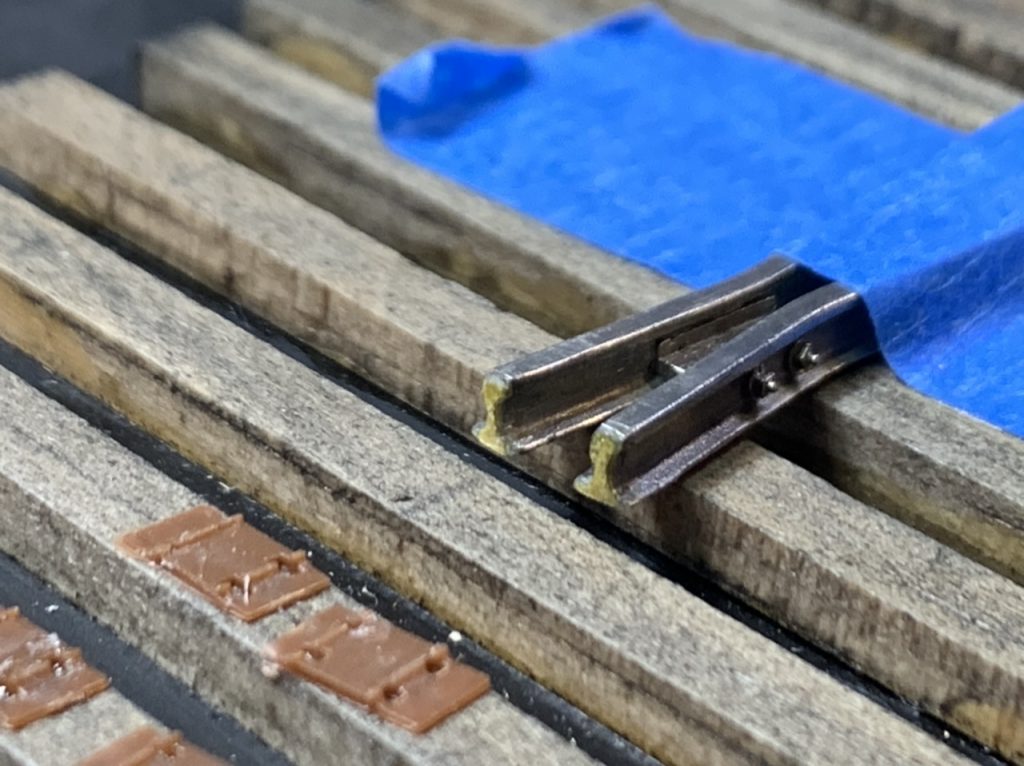
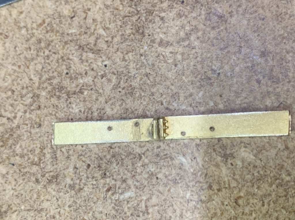
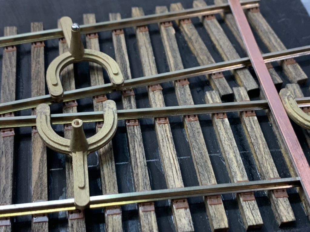
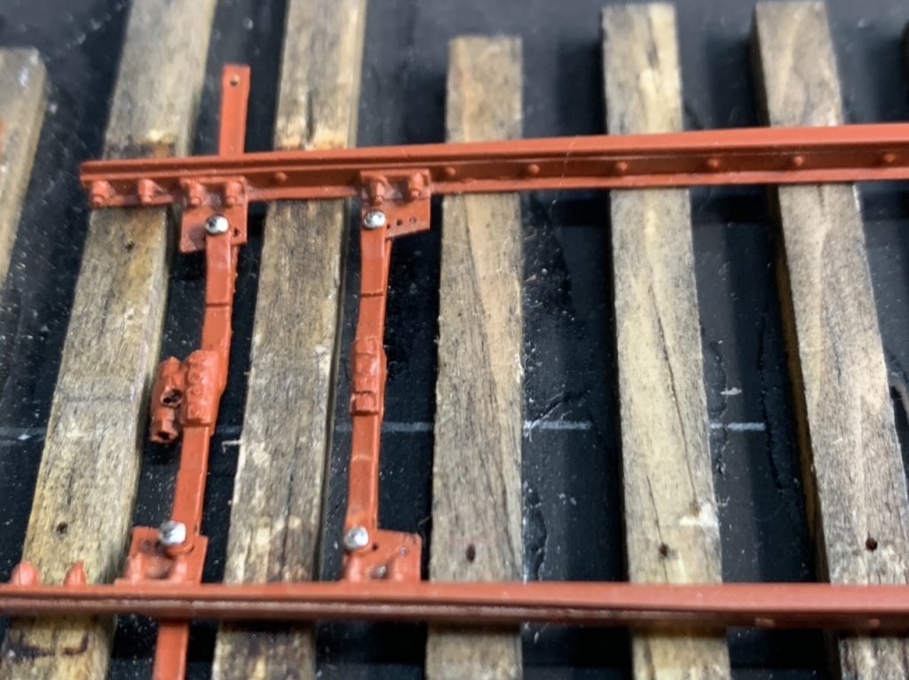
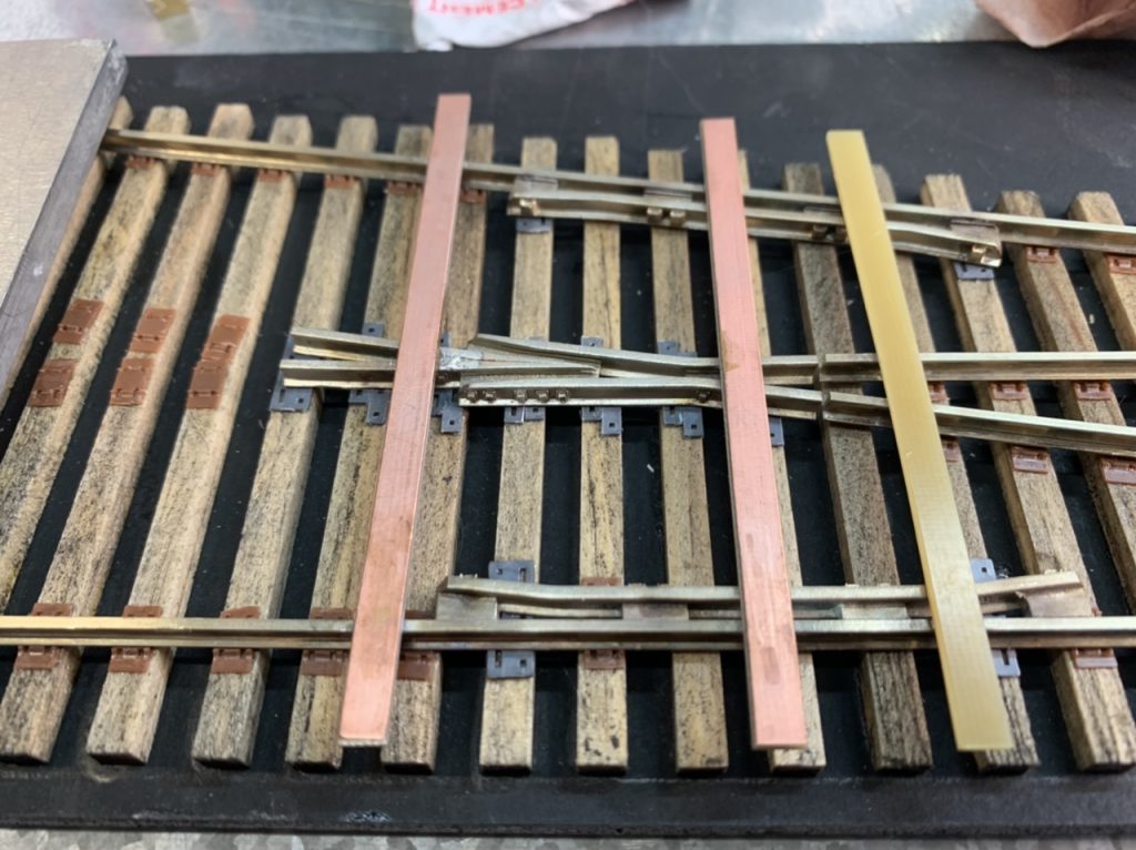
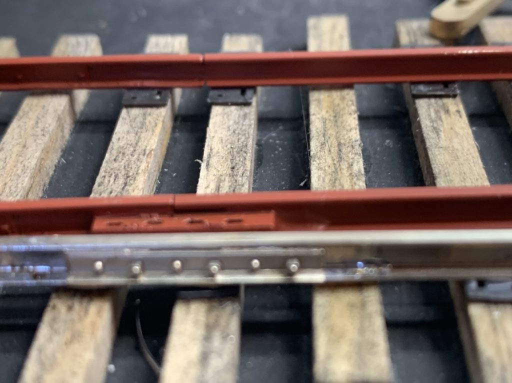
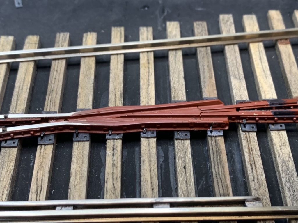
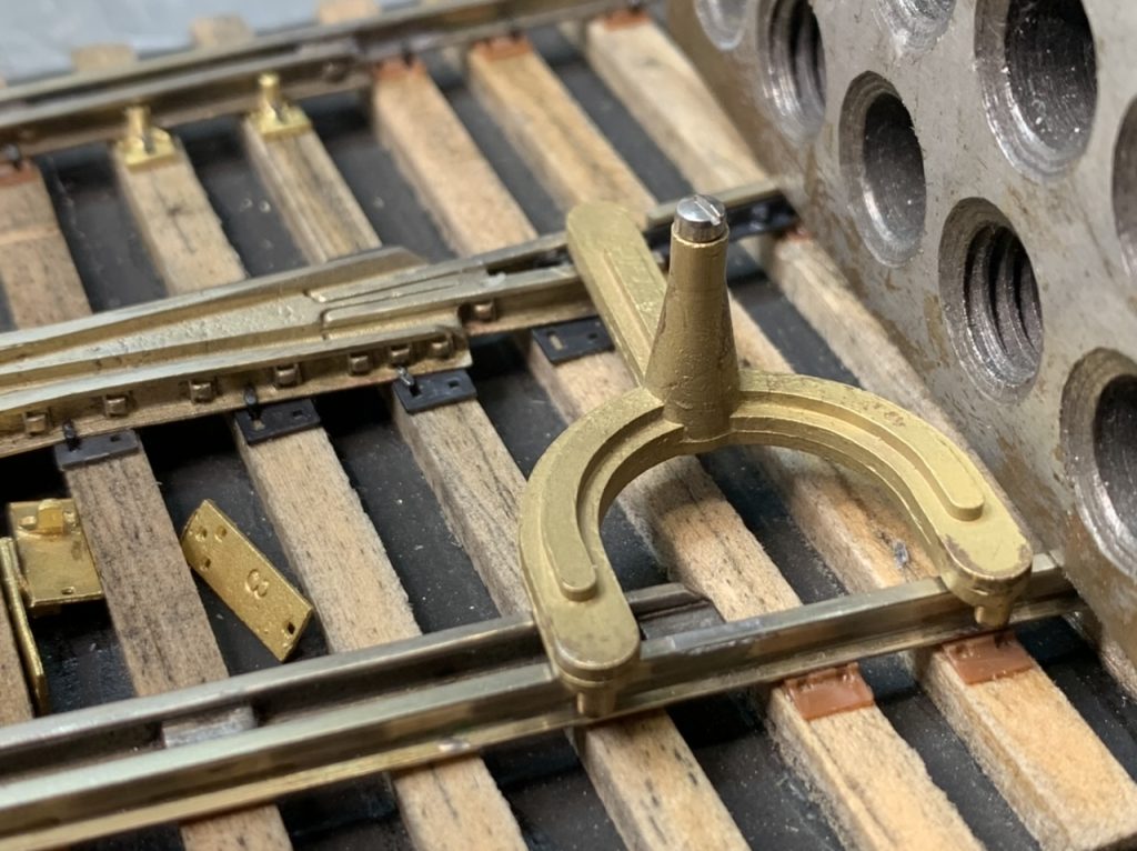
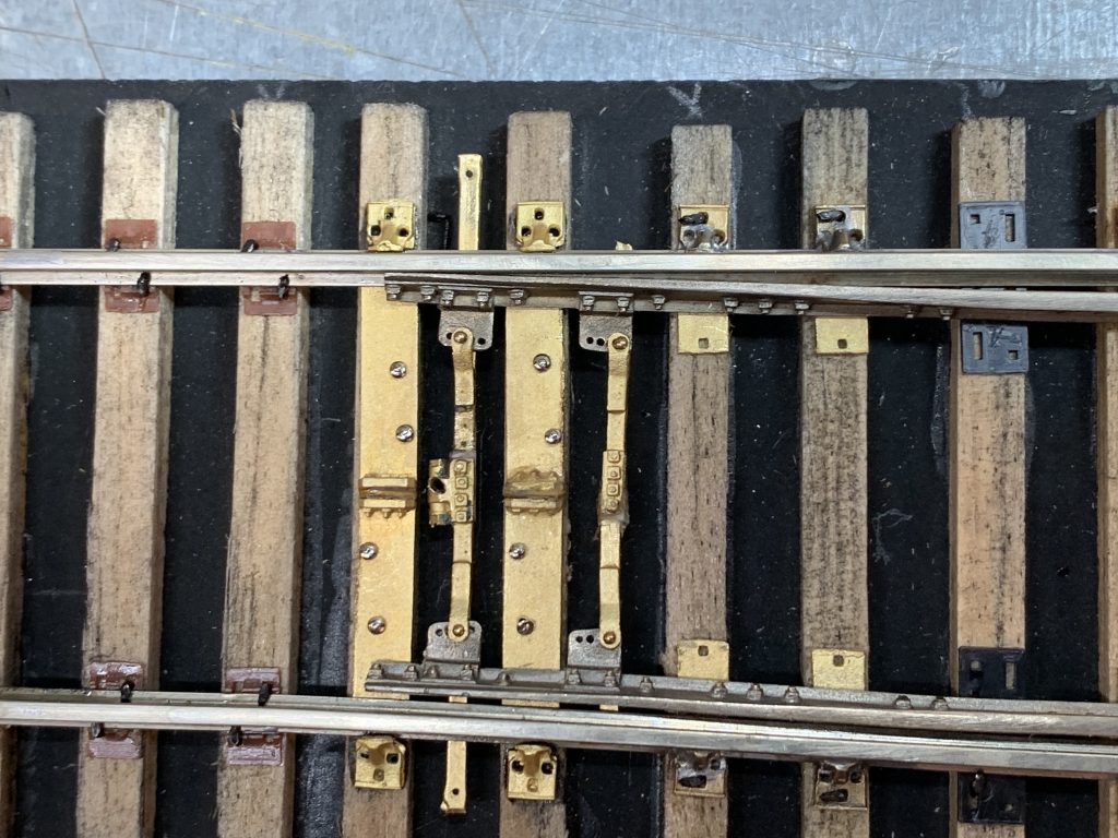
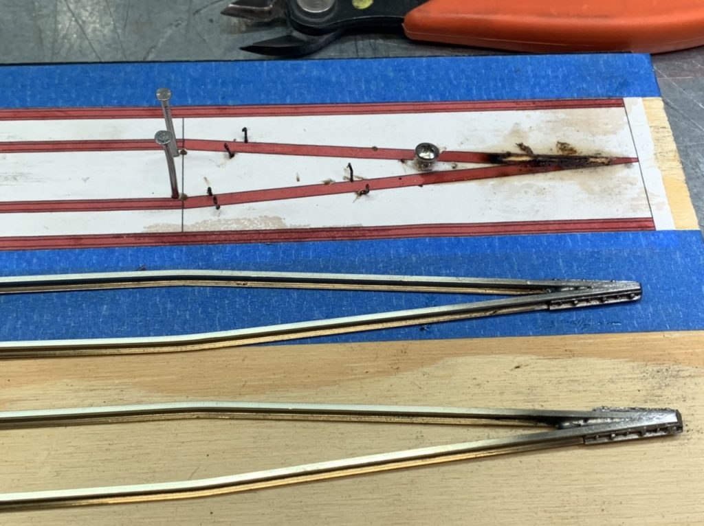
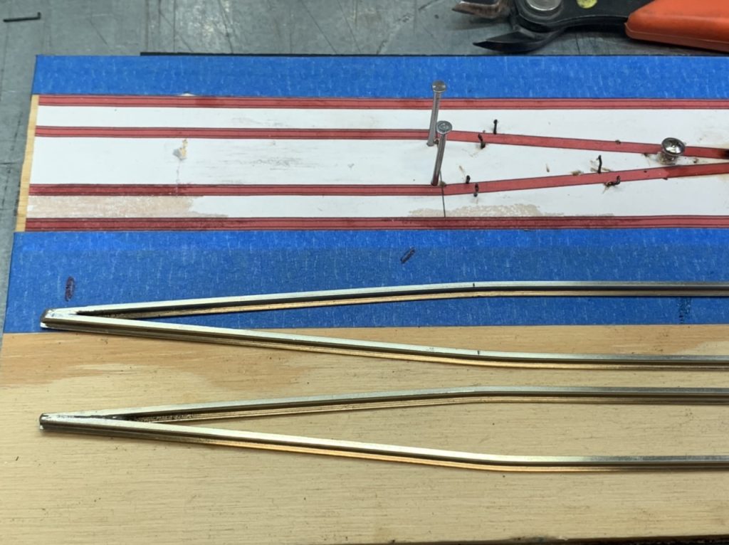
With the center yoke removed I was able to easily insulated, compress and glue the throw bars.
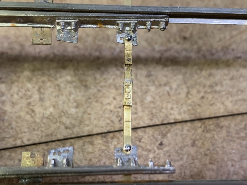
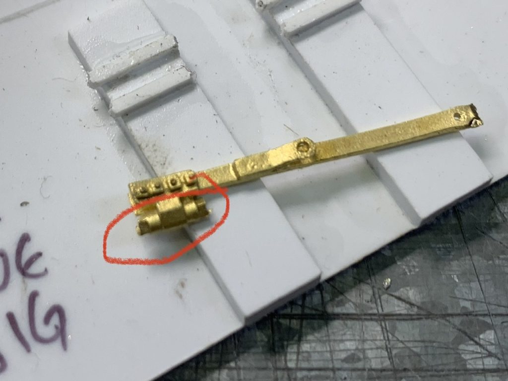
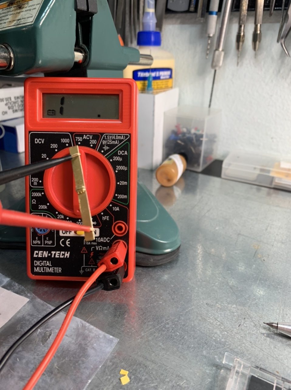
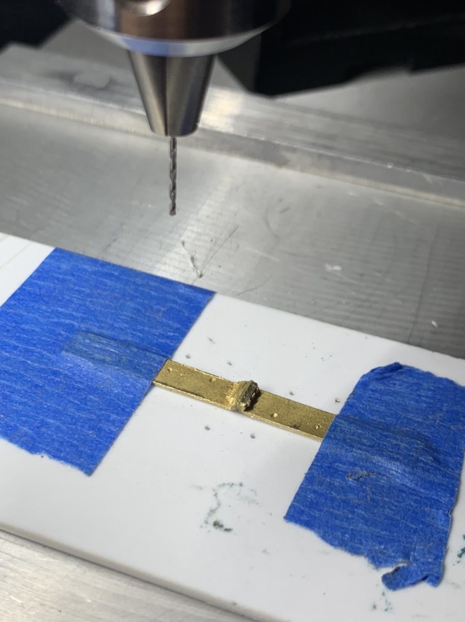
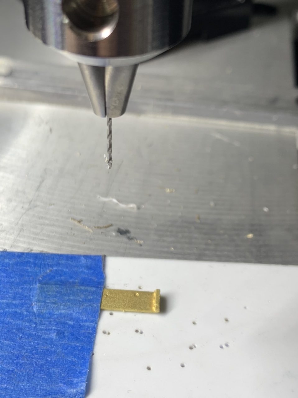
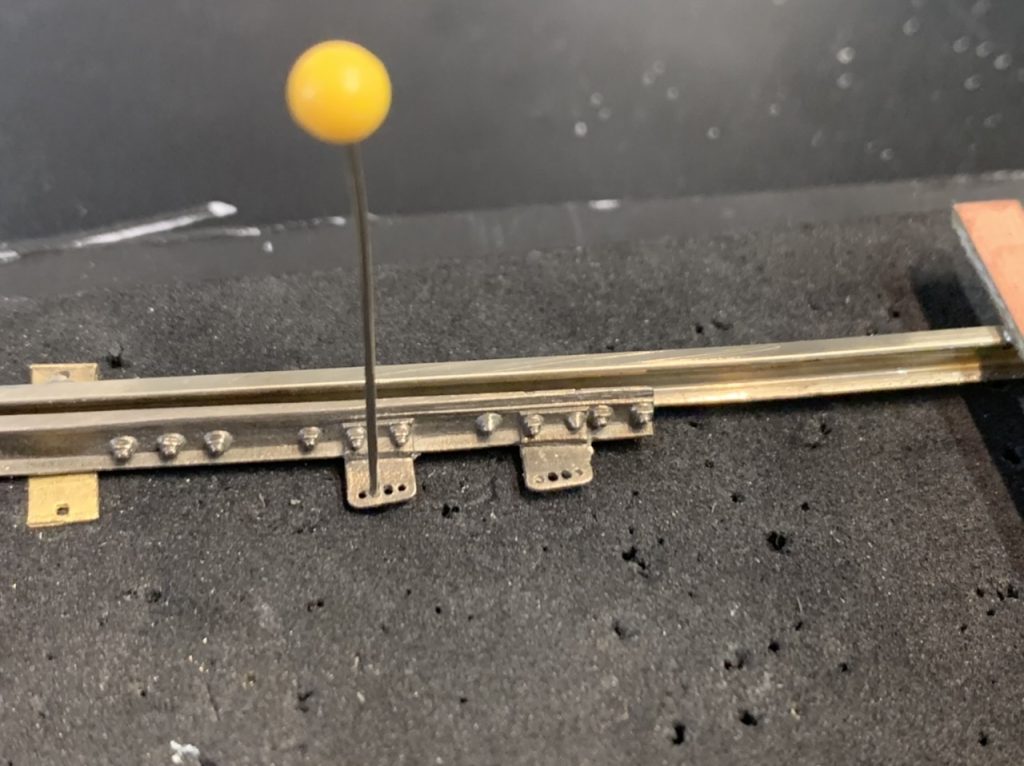
I think I’ve found a method to drill tortoise holes in the center yoke. Typically tortoise machines are driven by .033” (.85mm) or .047” (1.2mm) wire which is commonly available in USA. How large should I drill these holes? I’m thinking a 1.2mm actuating wire is probably the best solution here, but I’m not sure how much bigger I can drill the hole.
Other tortoise actuating options are:
- Using the horizontal hole that is cast in the center yoke. This may require a creative tortoise mounting method.
- using one of the holes cast into the end of the throw rod, these would need to be enlarged. And the tortoise would need to be offset mounted.
I’d like to mail down a solution before it’s completely assembled because it will be hard to drill these brass castings when they are installed.
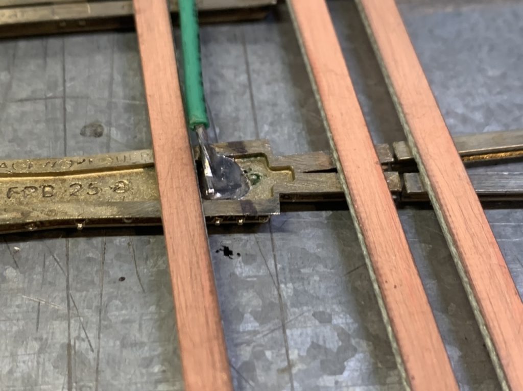
The Frog
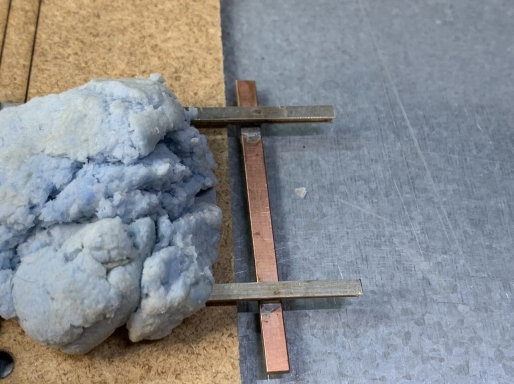
While I’m on the subject of the frog would you like me to solder some sort electrical contact to the bottom. I’m thinking either a wire pigtail or a strip of copper.
In closing I have 3 questions:
- What diameter of actuating wire do you intend to use with the tortoise motors? How large should I drill the holes?
- Do you like the insulating rail joiner/joint bar for the frog joints or should I continue to praise a separate insulating solution?
- Do you want me to solder an electrical connector to the frog to make it easier to wire when installed?
June 2, 2022
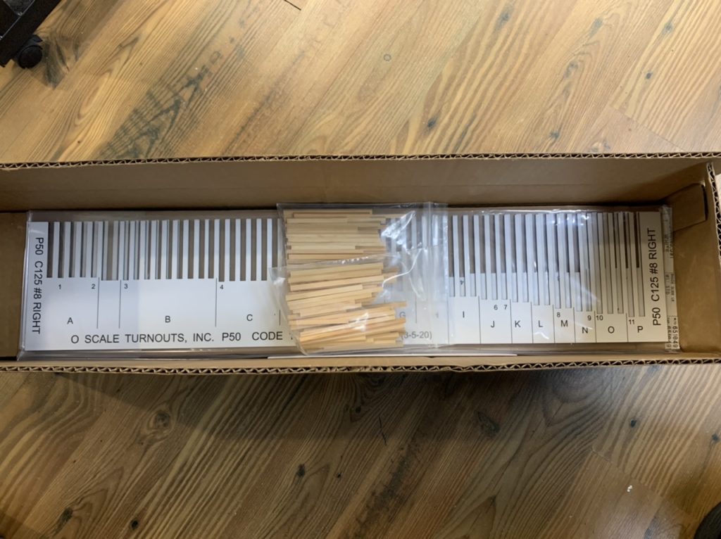
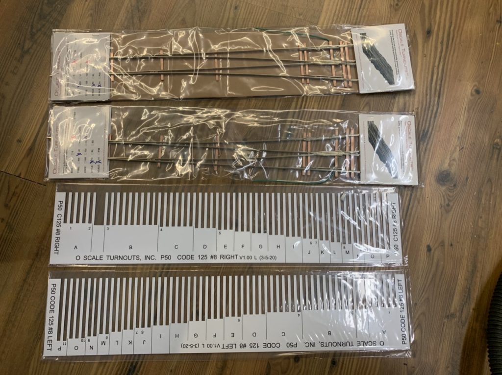
I continued to work on the throw bars today. And the package from O Scale Turnouts arrived.
June 3, 2012
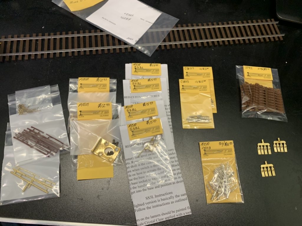
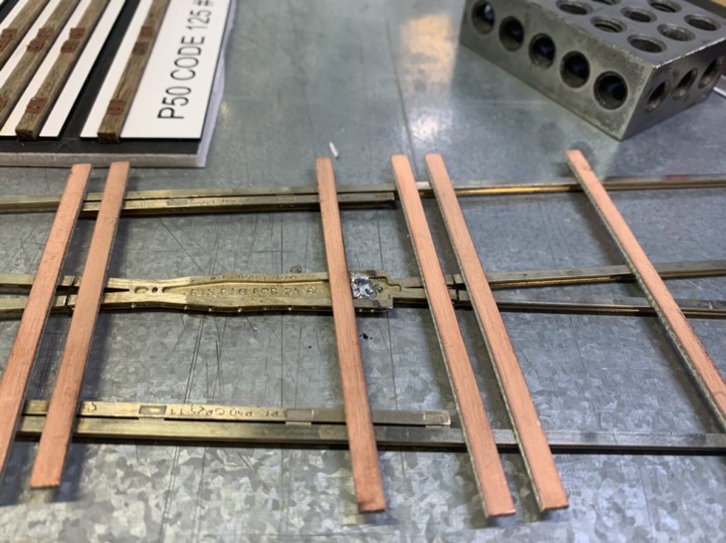
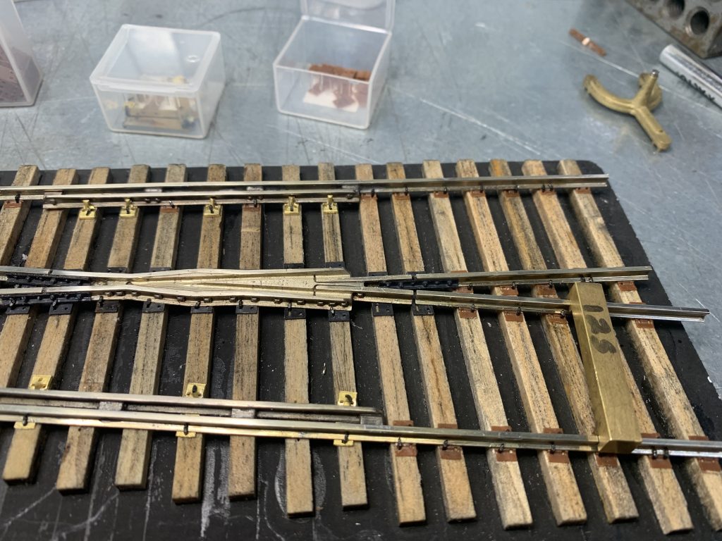
I received a delivery from right-o-way today. It included 2 – PMM Pittman motor mounts, 4 – SS3L switch stands, 2 – CBJ 125 Compromise joint bars, 30 – RCM 1503 Rail Joiners. Jay also included miscellaneous throw bars, rail braces and flat tie plates.
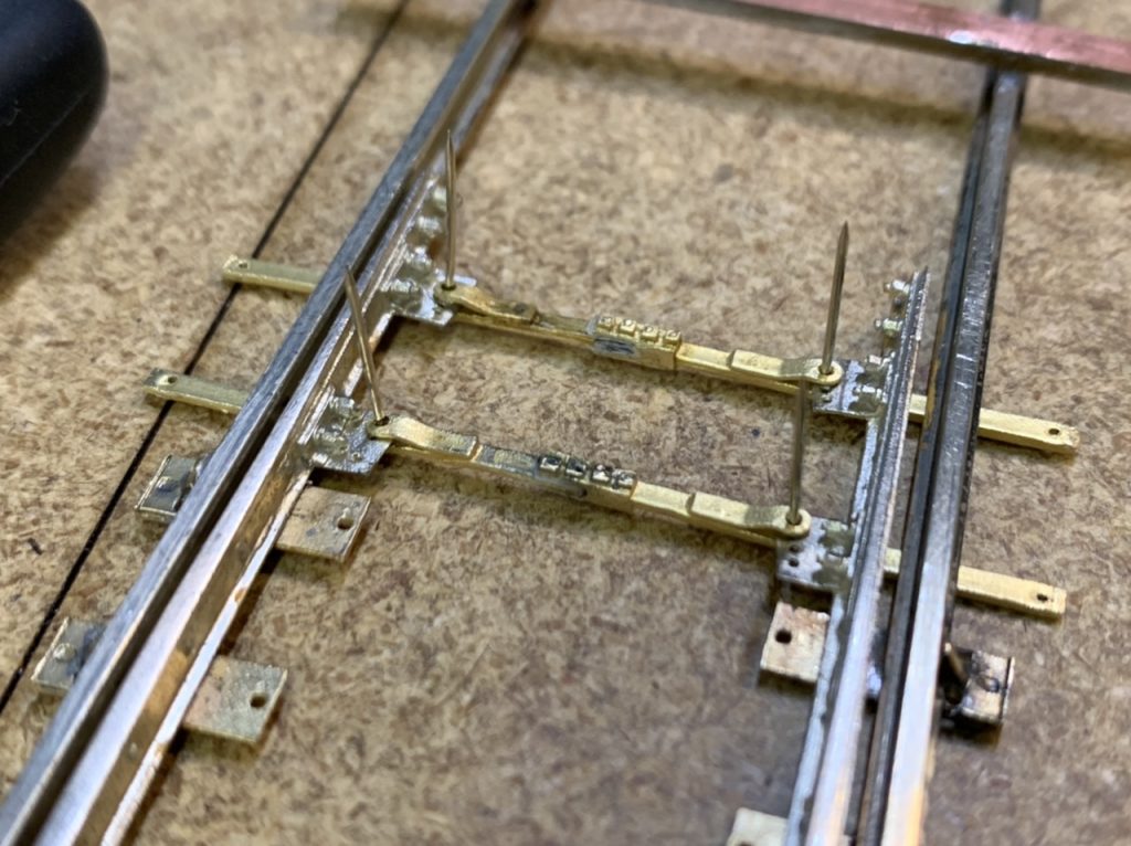
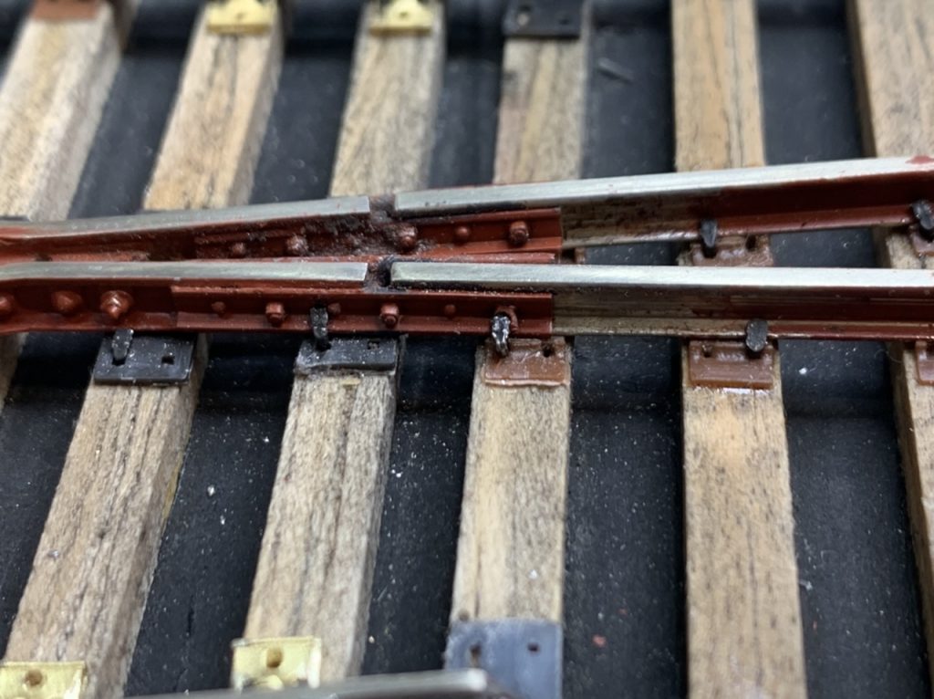
I added the front throw bar to the #6 L turnout.
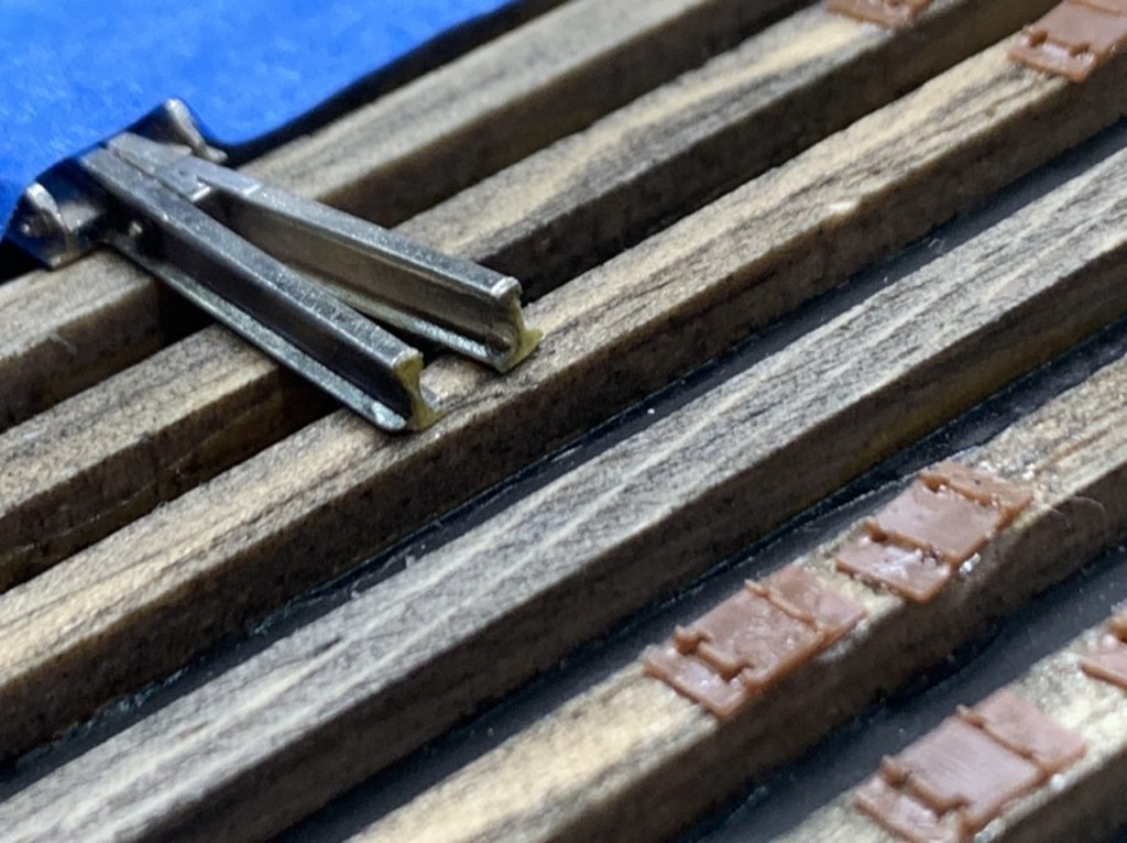
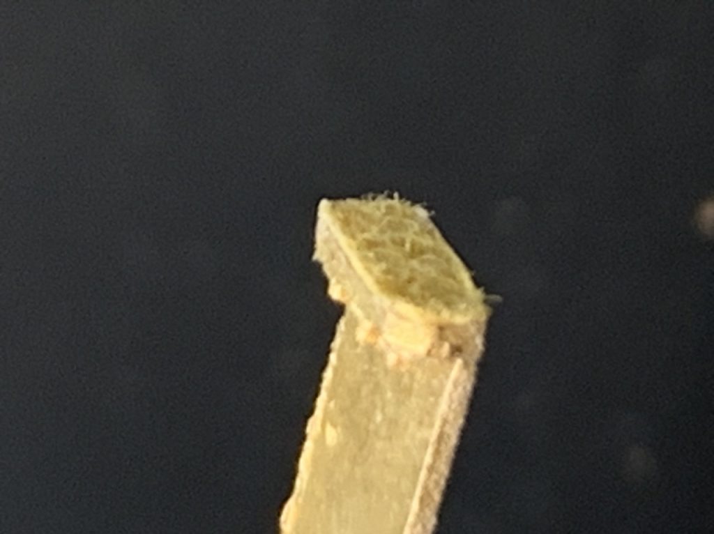
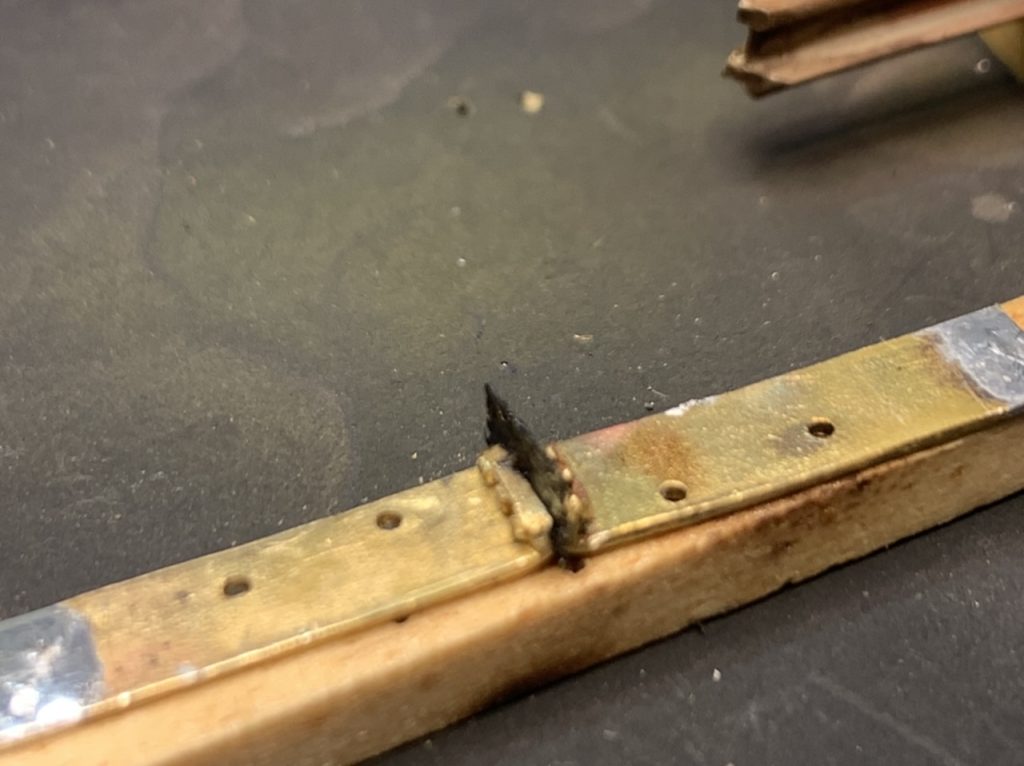
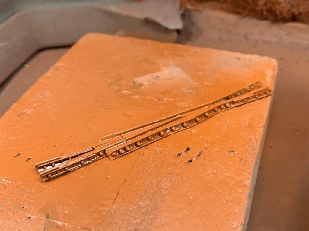
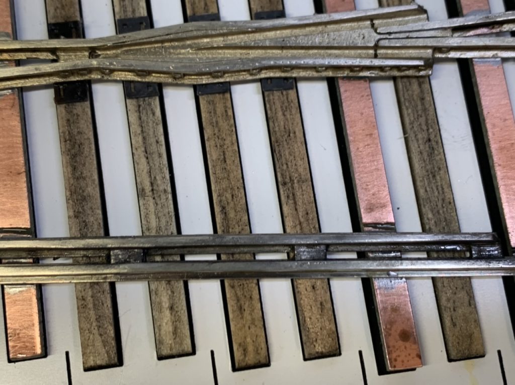
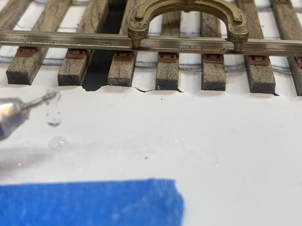
I insulated the frog using paper and CA.
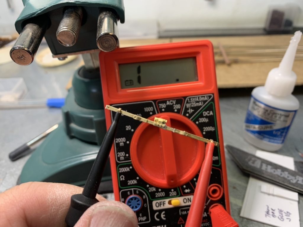
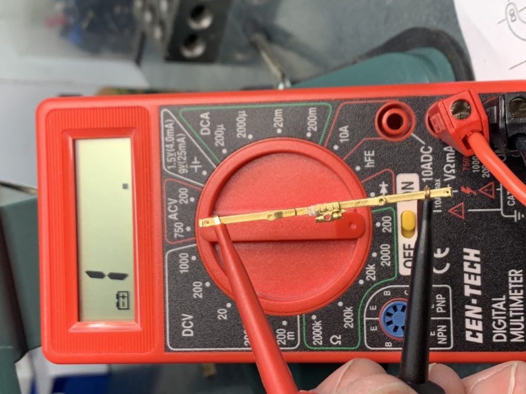
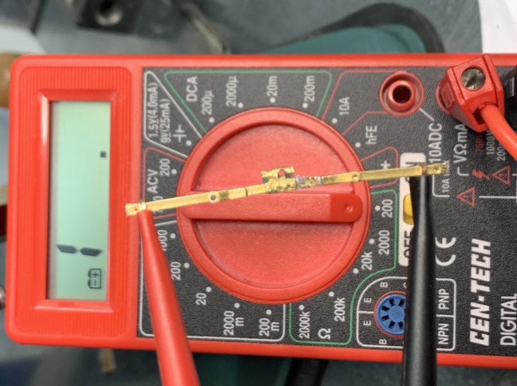
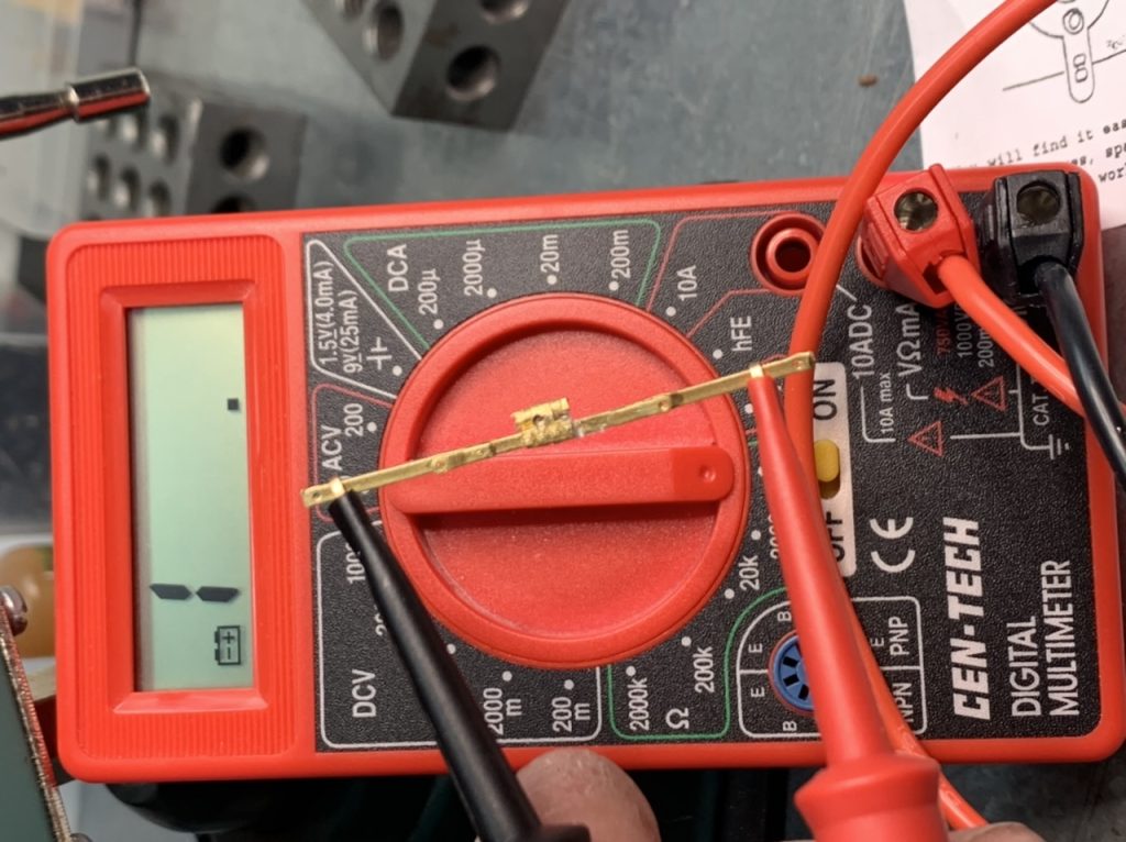
I worked on the rear throw bars. I removed the center yoke, insulated and glued them together. I checked each one for electrical insulation.
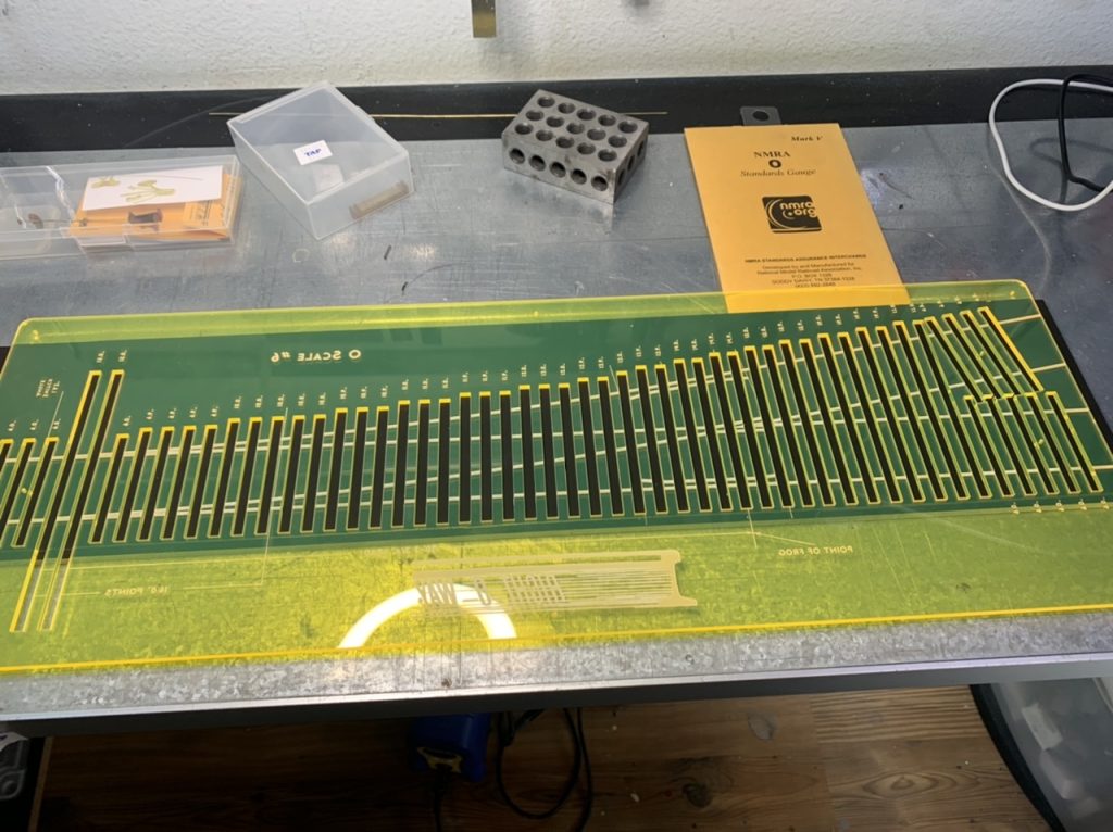
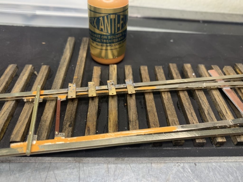
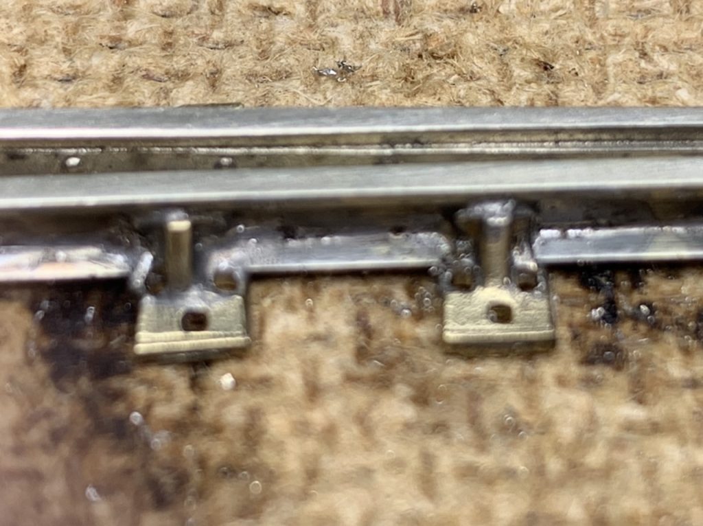
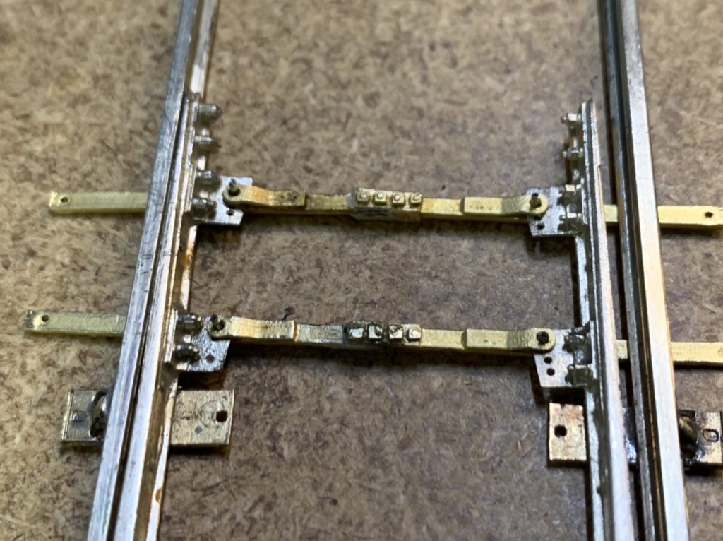
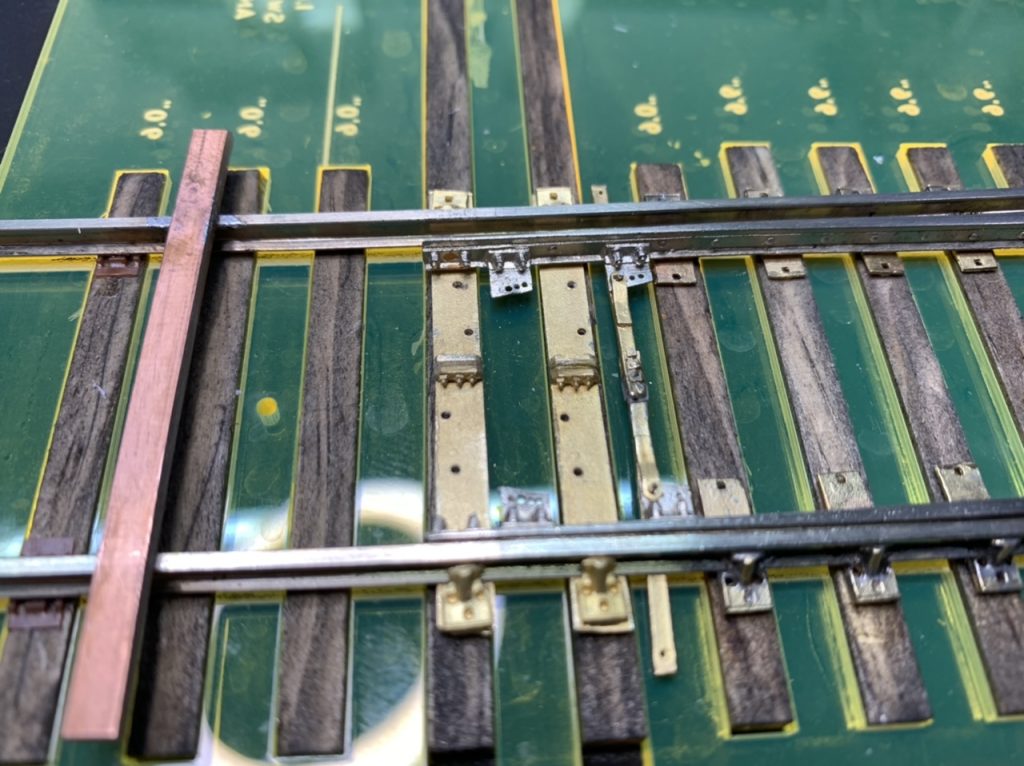
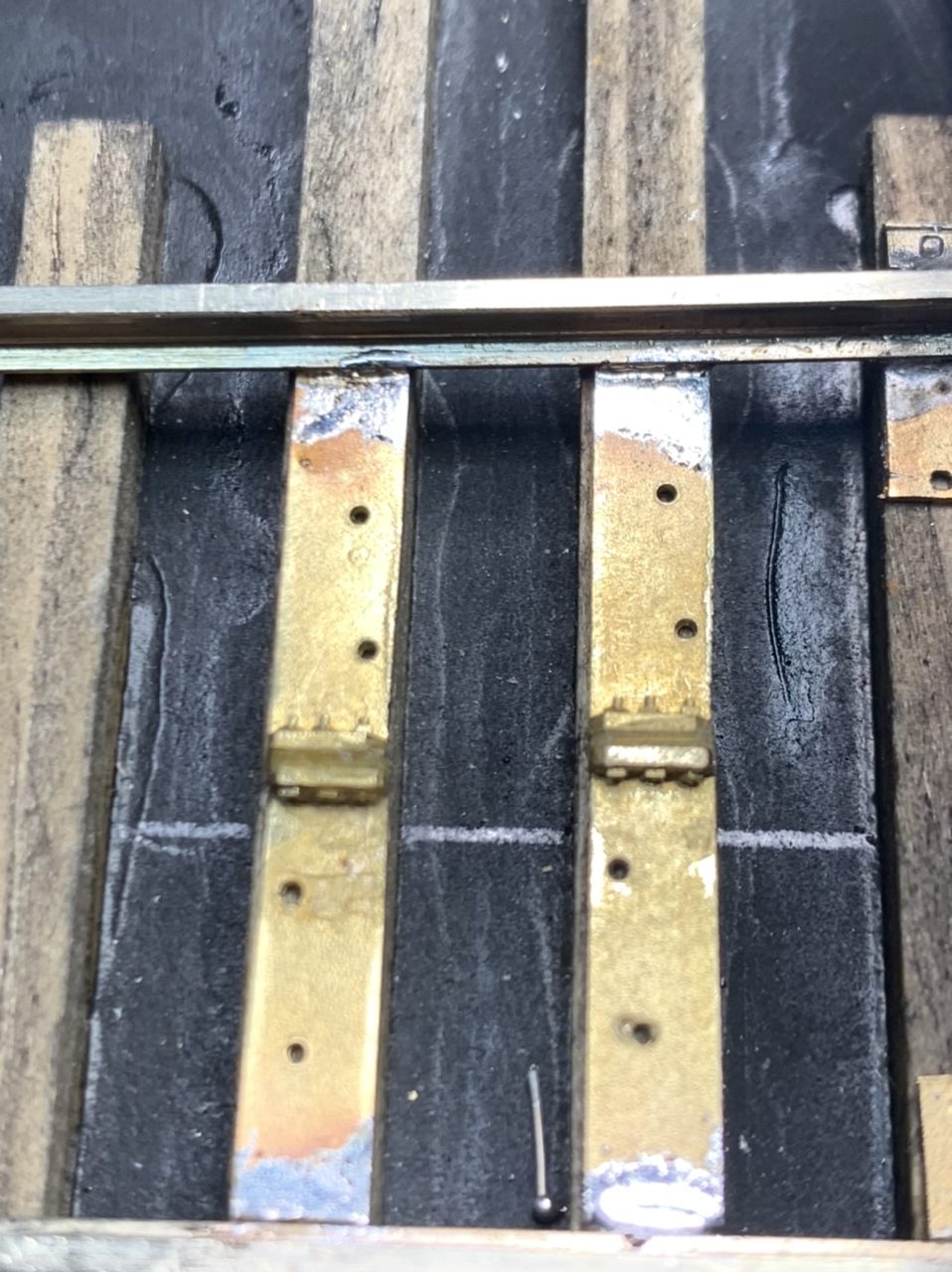
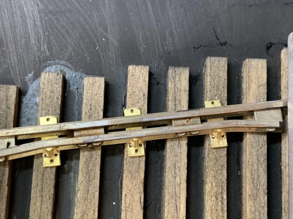
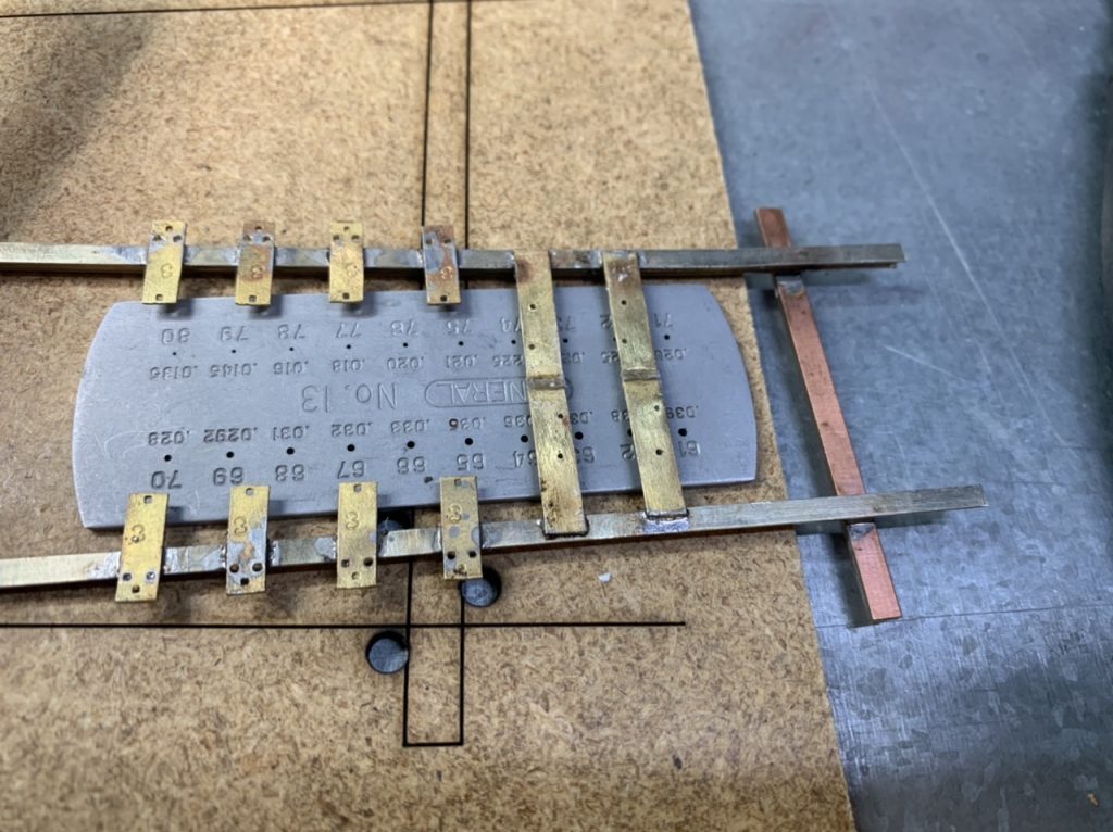
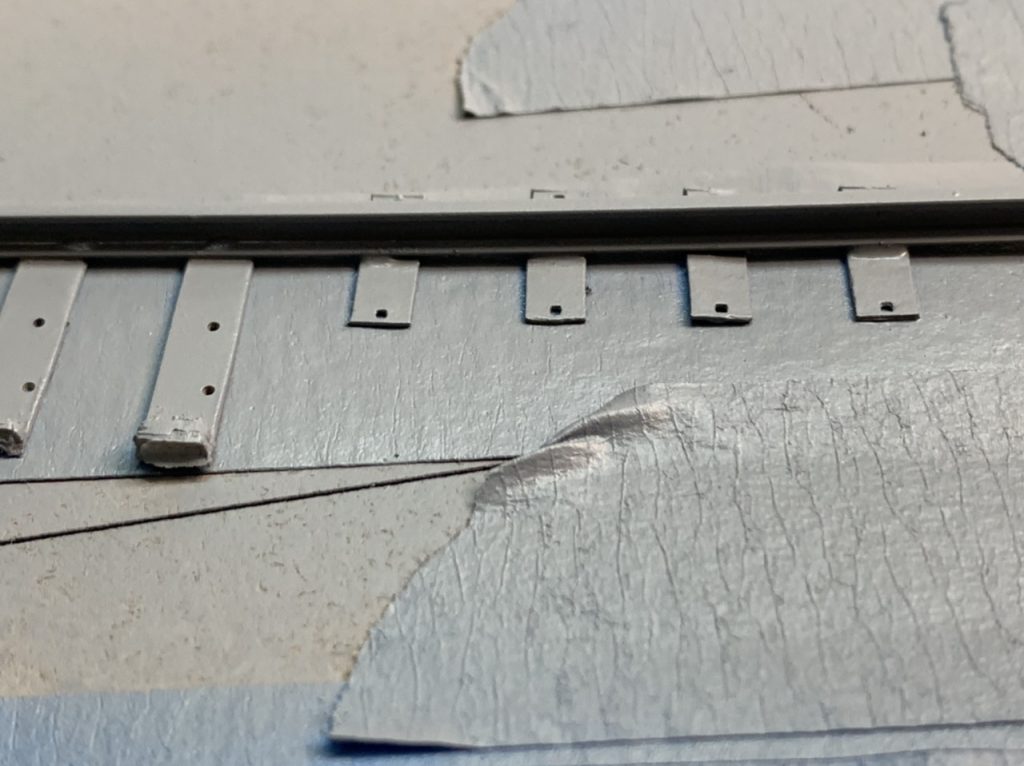
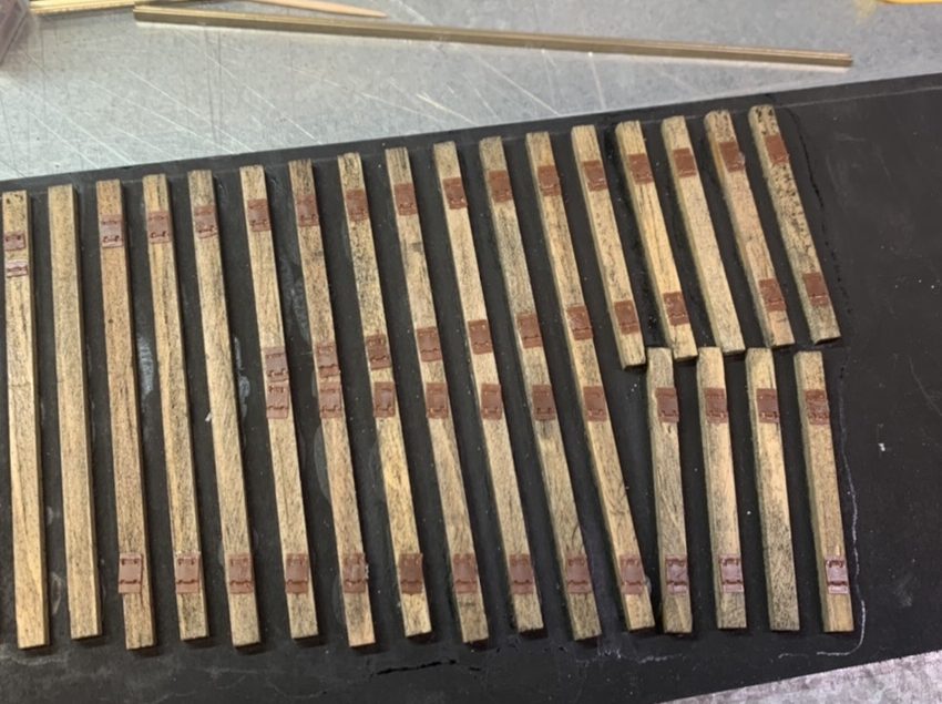
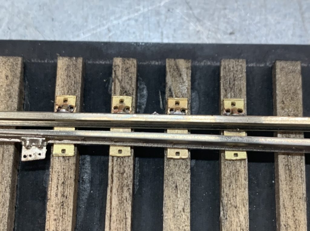
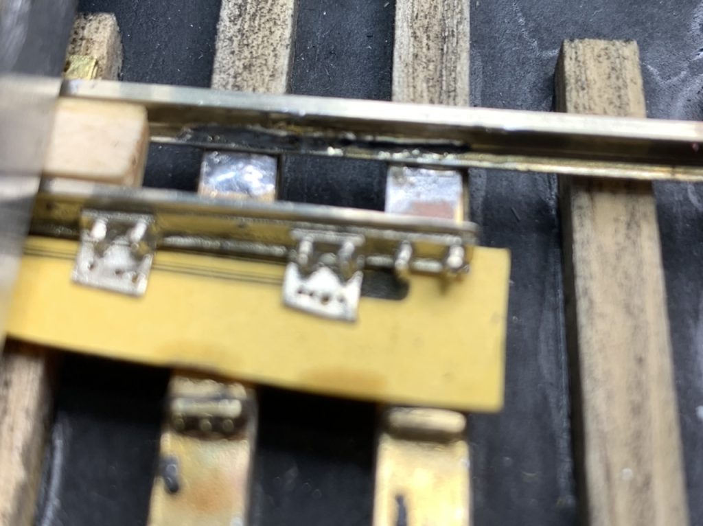
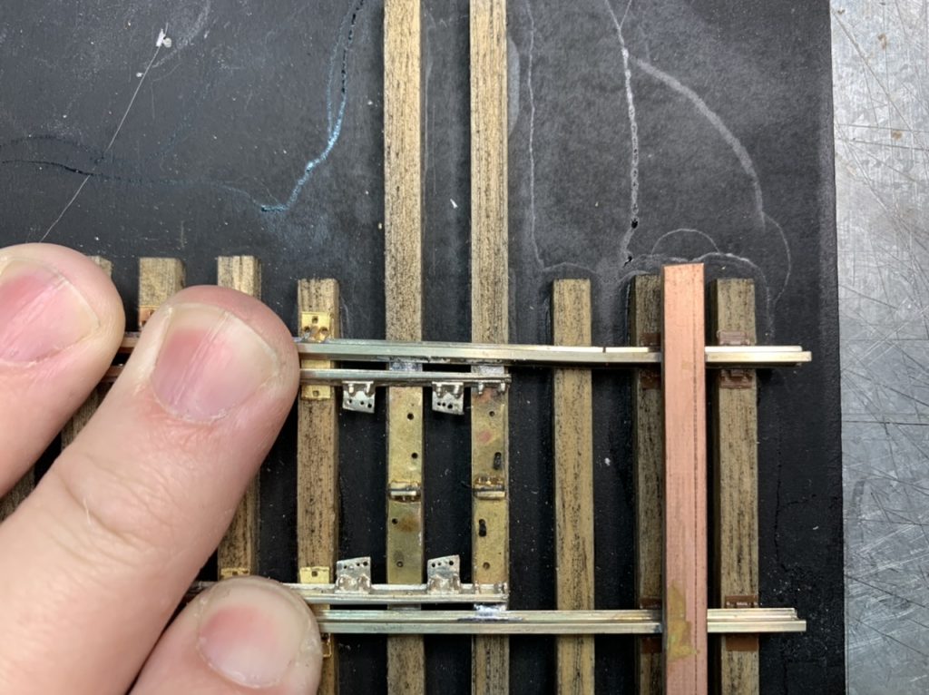
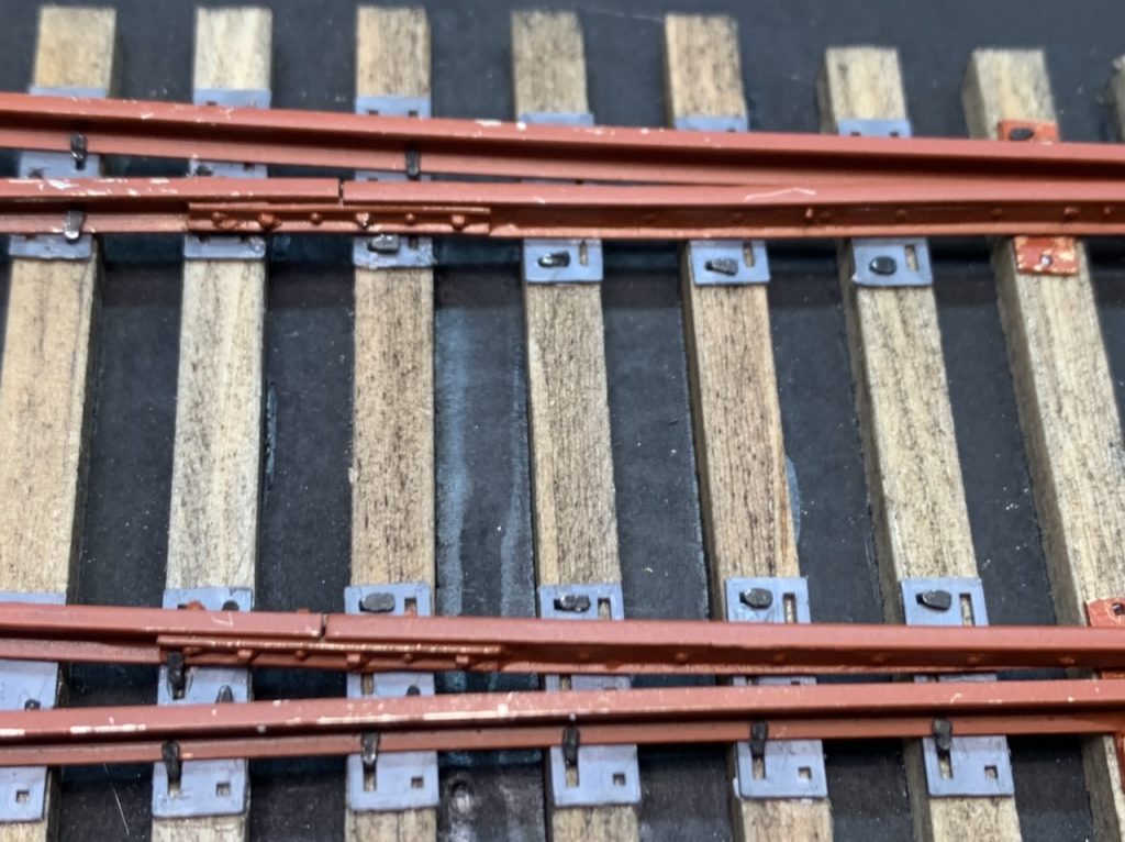
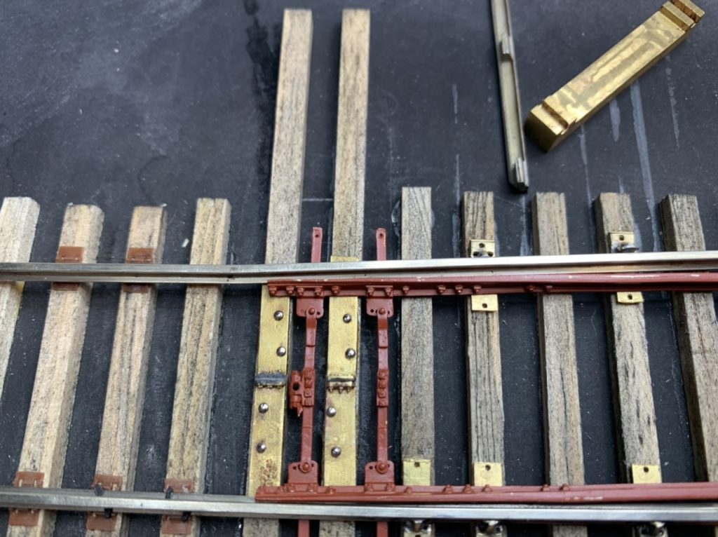
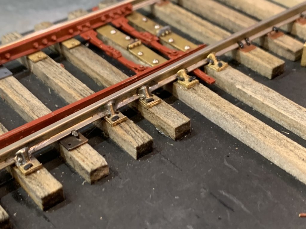
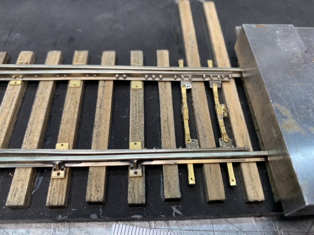
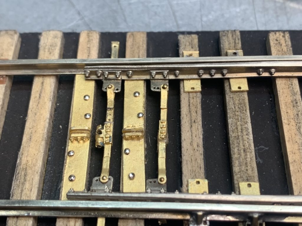
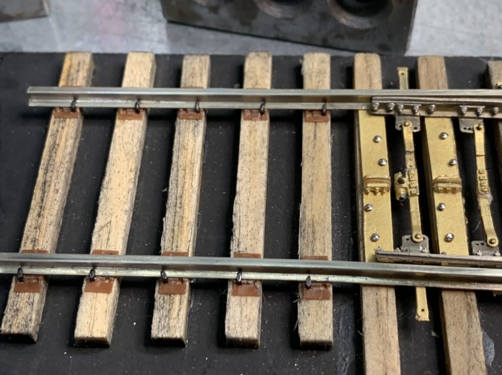
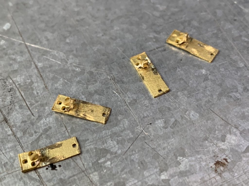
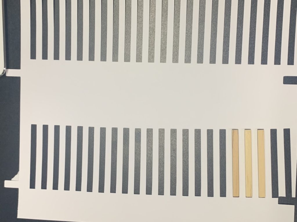
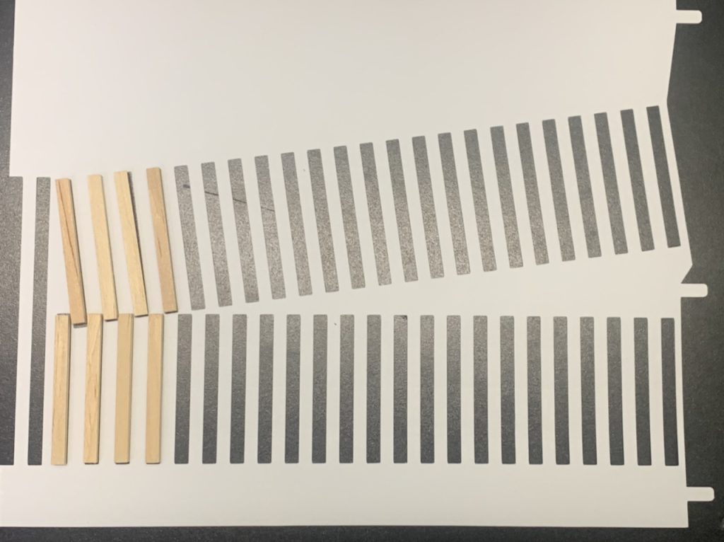
I worked on the gauge plates. Each plate needs to be insulated, glued, filed clean, drilled out and checked for electrical insulation. These will be cut to fit the turnout and have a rail brace positioned on the outside rails. I have done the initial prep on 4 of 8.
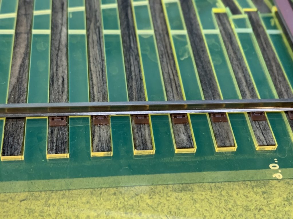
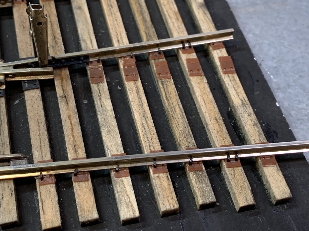
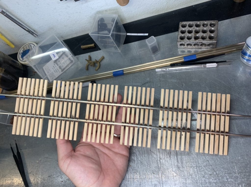
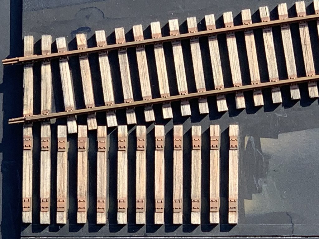
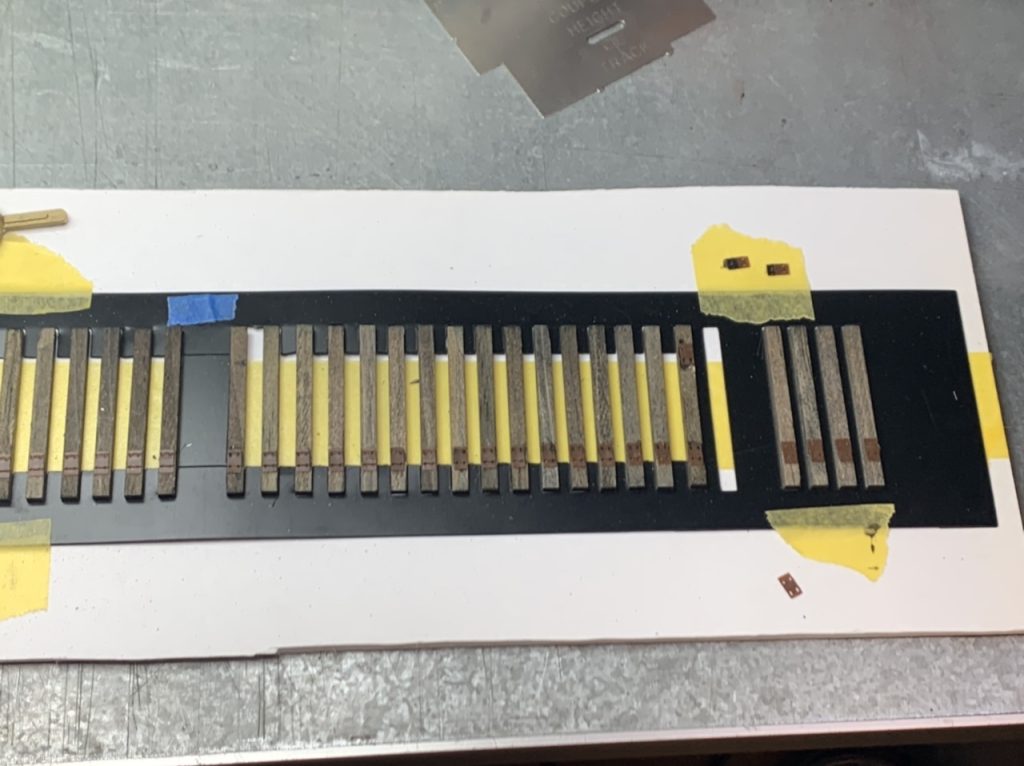
I started laying in tie plates today. The remaining plates will be positioned while the turnout is being spiked. This has also allowed me to remove some of the PCB ties from the kit assembly.
June 4, 2022
More work on gauge plates. Beginning work on the #8 turnouts.
June 5, 2022
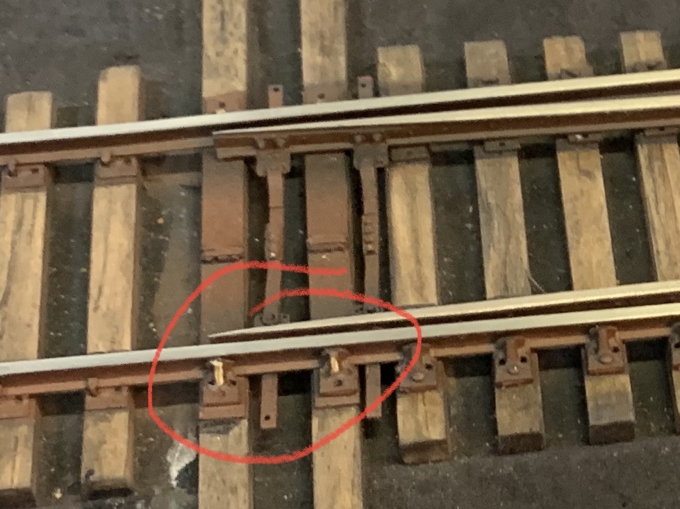
I wasn’t happy with the gauge plates I installed yesterday so I removed them and am reworking them.
I also discovered that the CA joint between the gauge plates was failing from the heat of soldering the parts.
I’m thinking ahead to finishing. My turnout was primarily finished with acrylic primer and paints. It is relatively robust, but it has chipped in places. I like to develop an even more robust process.
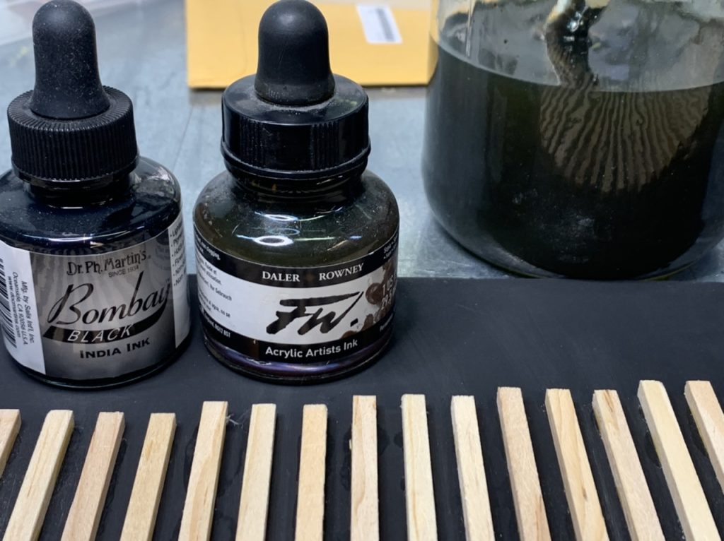
I conducted an experiment with blackening solution. I wanted to see if primer would adhere better to the blackened metal pieces and I wanted to see if the underlying blackened metal would show through if the primer was chipped off (instead of nickel silver or brass color).
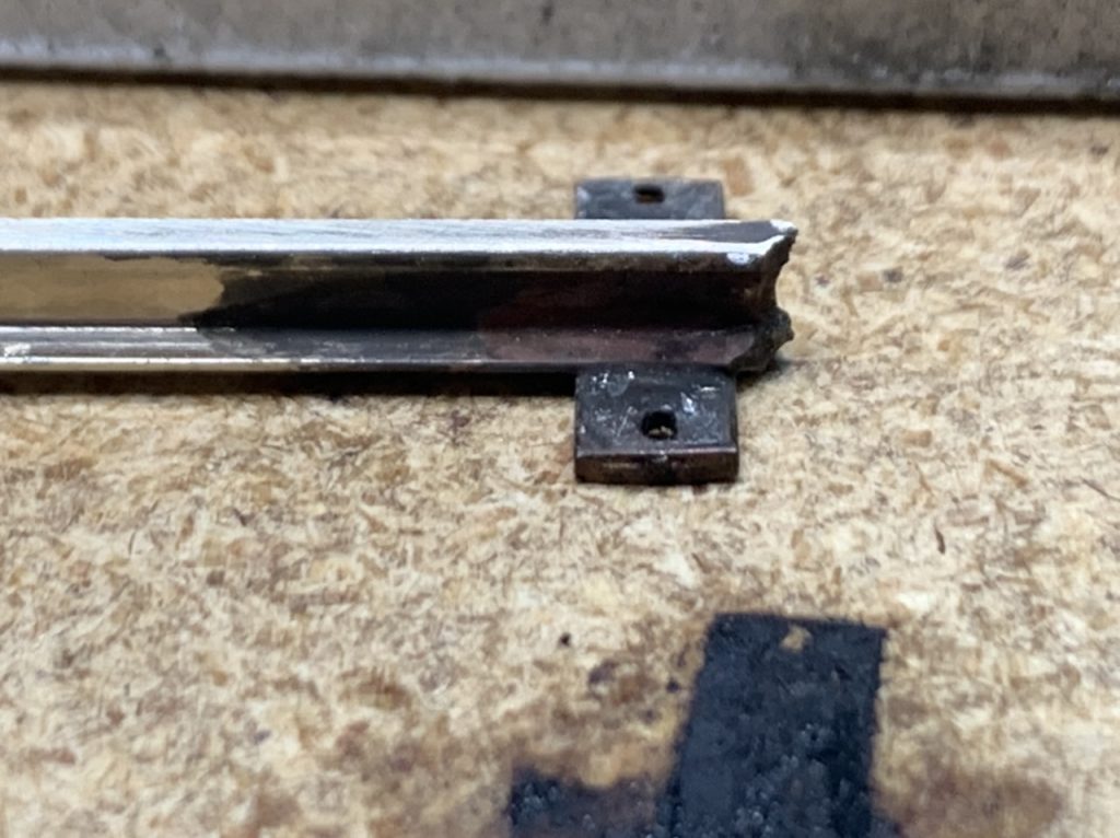
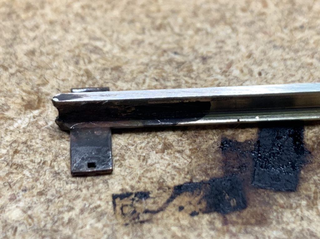
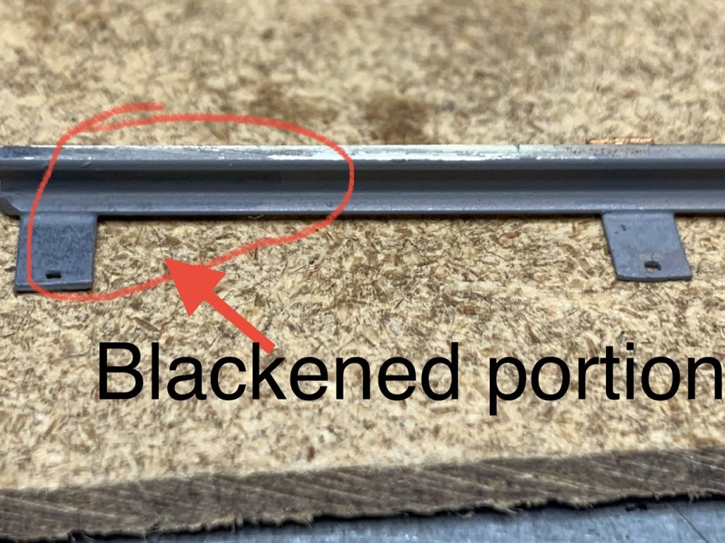
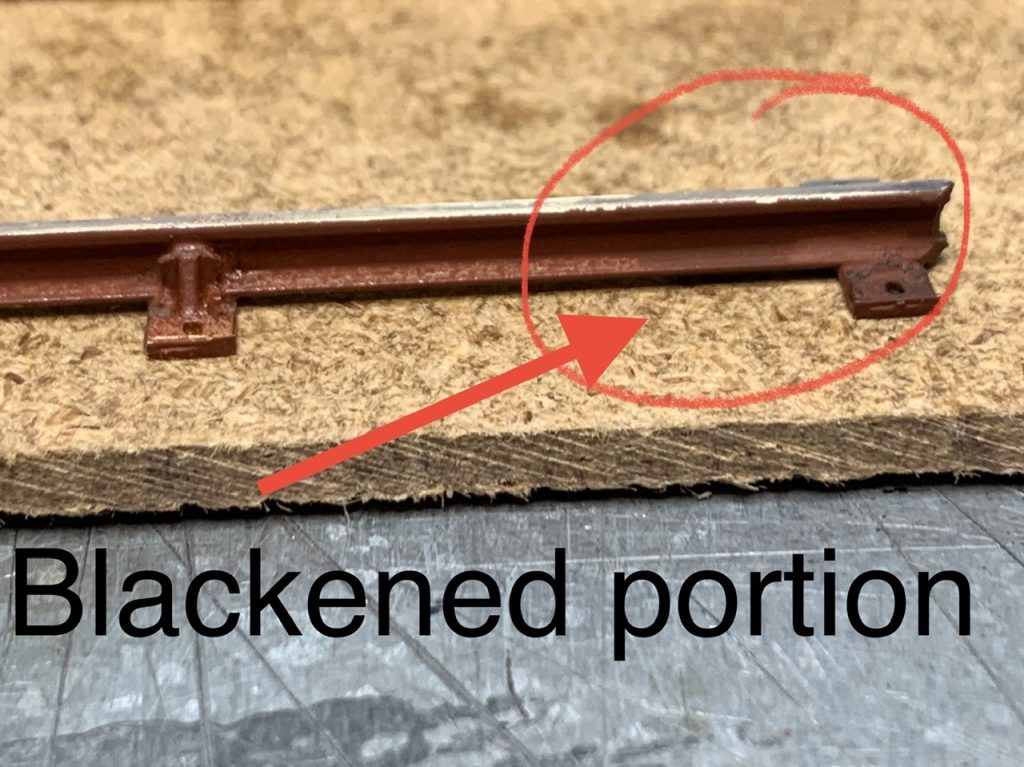
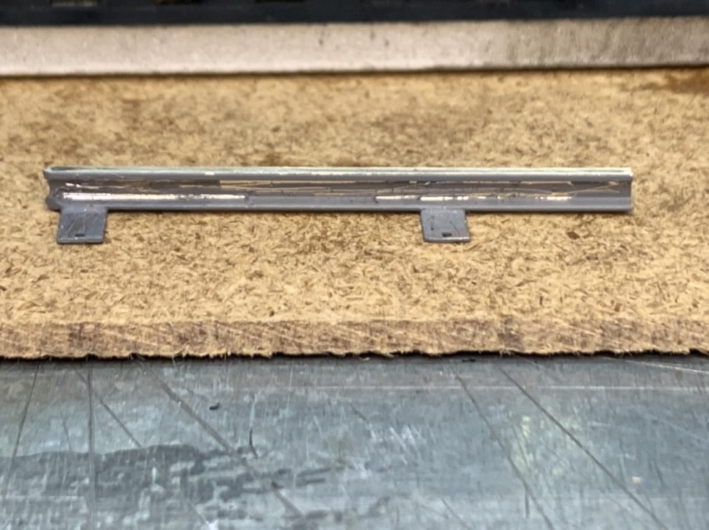
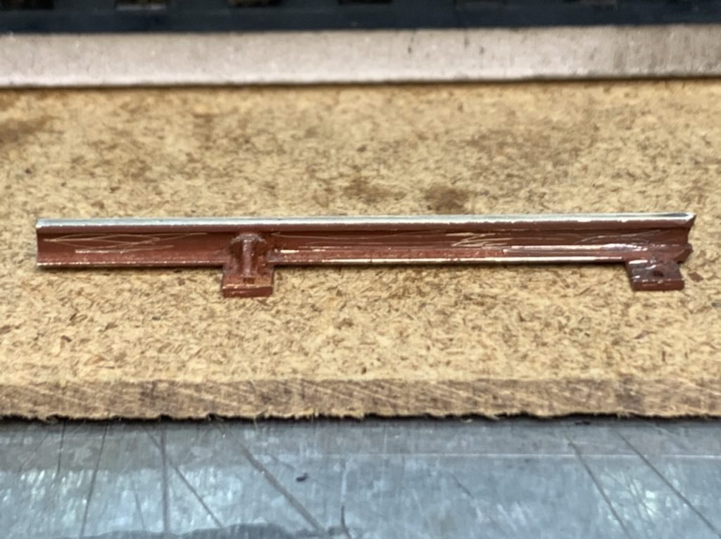
Although the blackened metal color did not hold up when I scratched the parts with a razor blade, the paint did appear to adhere better to the blackened portion of the rail.
I’ll be doing more experimenting.
June 6, 2022
I continued work on the gauge plates. Epoxy to connect the plates was a fail. I solved the problem of the soldering heat destroying the CA bond and decided to go back to using CA but with a fresh bottle.
Gauge Plates
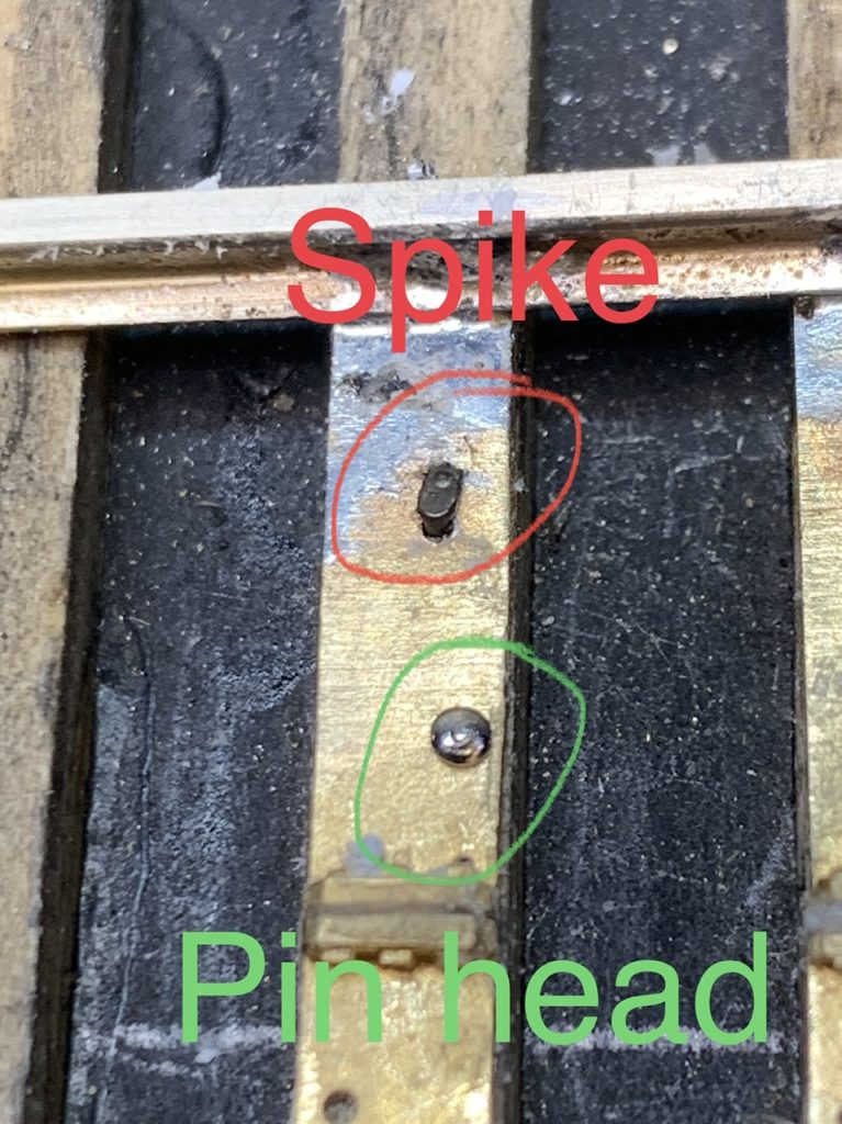
Question? Should I use the pins, the spikes or find something different?
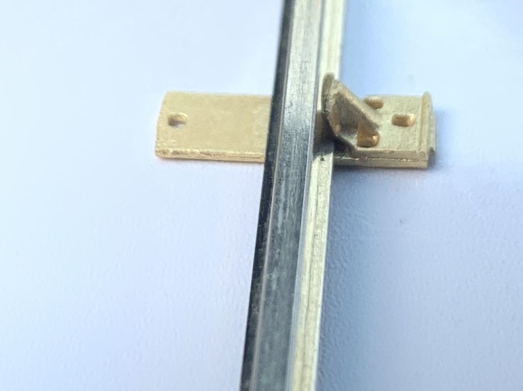
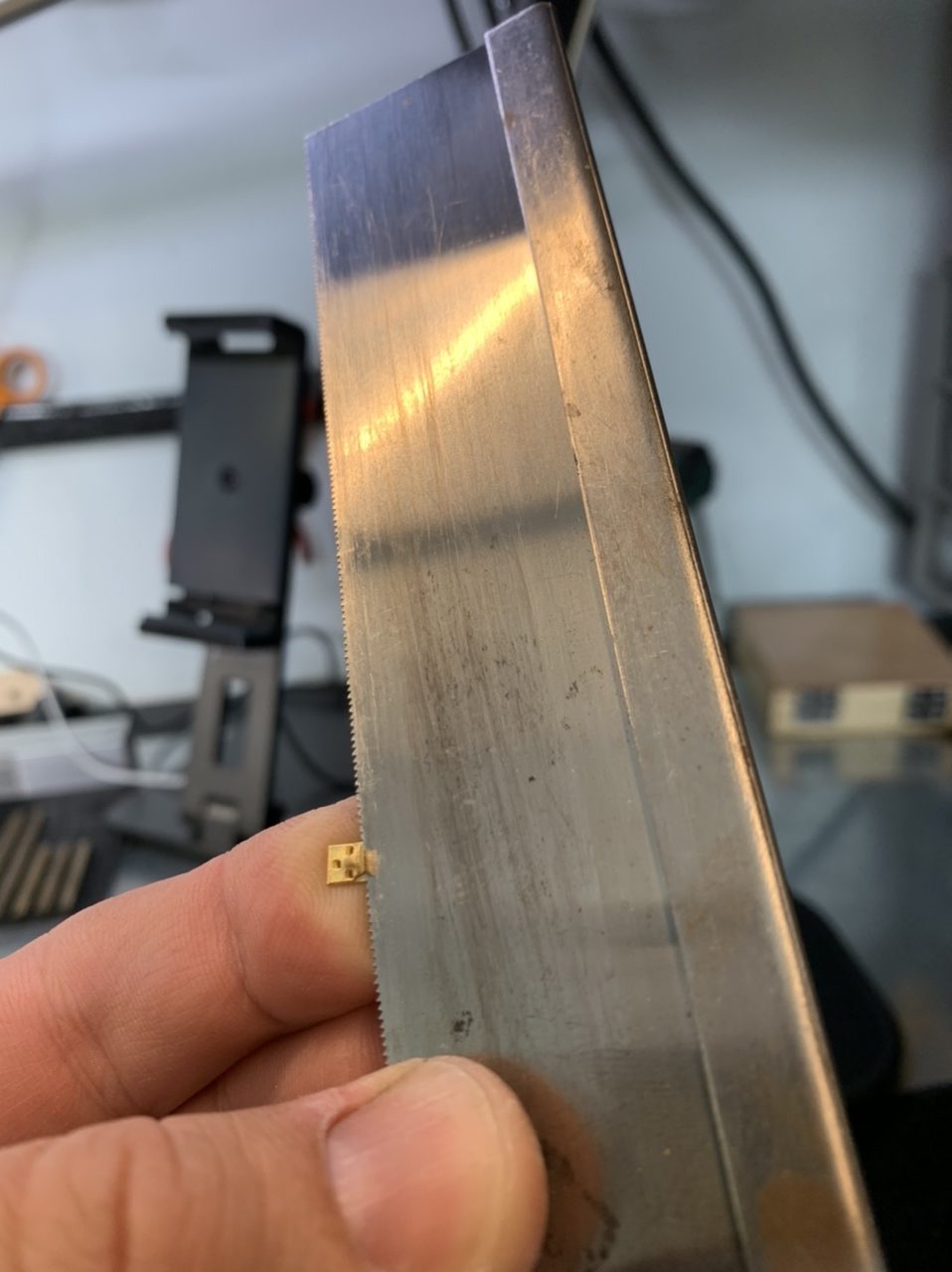
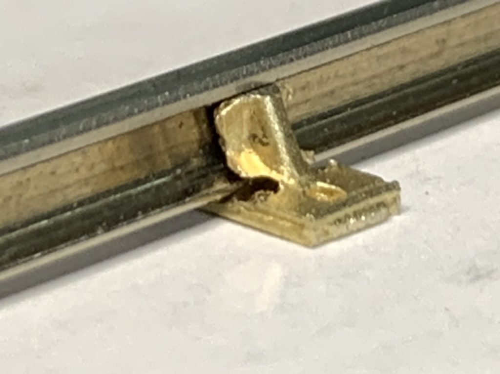
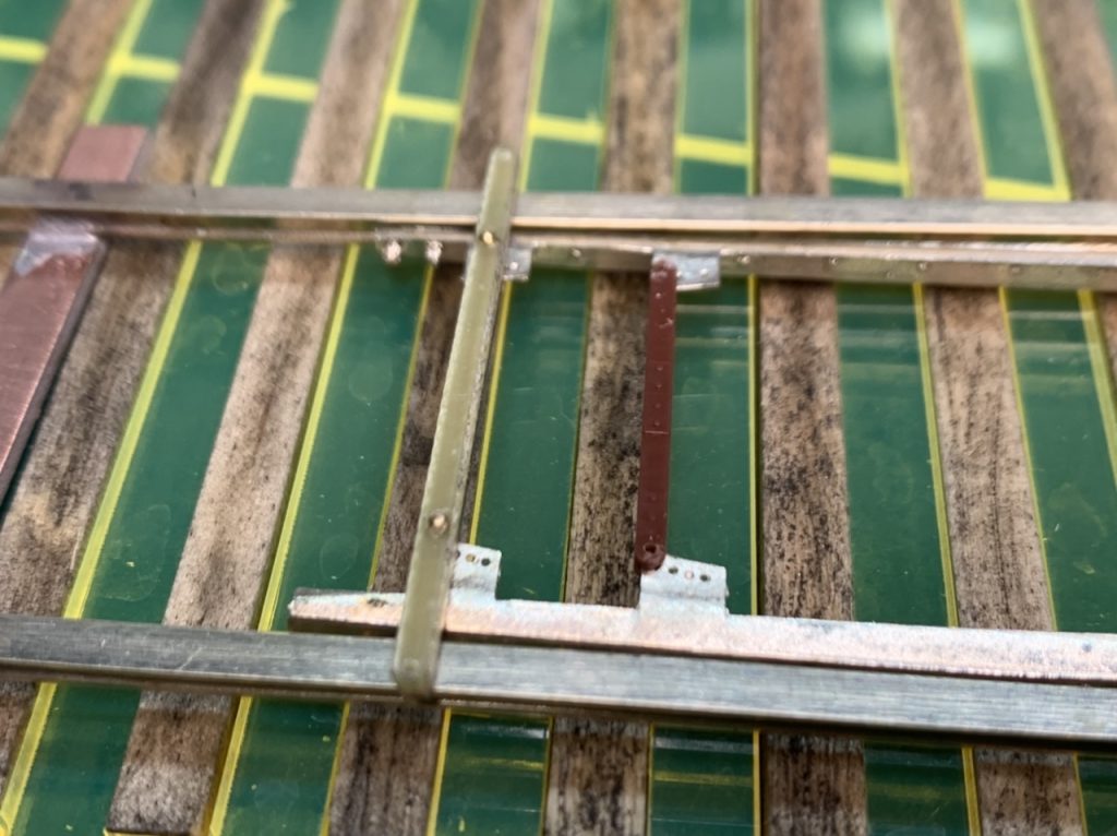
Guard Rail Bracing Question
If you recall my turnout, I used rail braces to represent a double plate braced guard rail. I did this to simulate the look of some of the modern turnouts I see day to day. It’s more artistic expression than prototypical accuracy.
The reason I mention it is that as I was going to solder these rail braces on your guard rail and it just looked strange to me. The diagonal overhang from the ties is severe. The outside braces sit in the kinks in the guard rail. The braces need to be spread out to not obscure or destroy the bolt head detail on the guard rail.
Simulating this with the turnout I built looked just ok to me, but I had a different type of guard rail. With very little cast in details aside from bolt heads at each end. Your guard rail is more detailed with bolt head detail in four locations. So simulating a double brace plate isn’t possible.
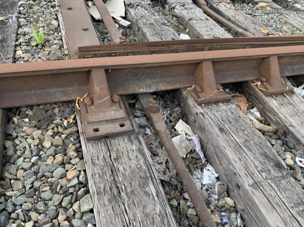
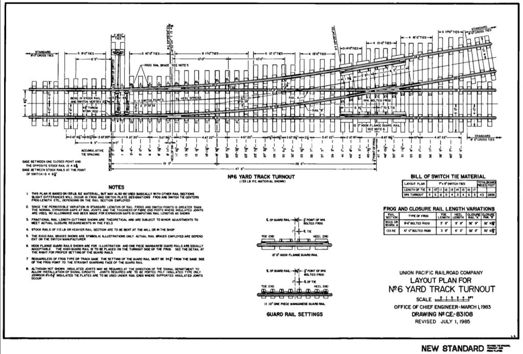
I checked a #6 diagram from the Union Pacific in 1985 which shows double plate braces with a cast manganese frog.
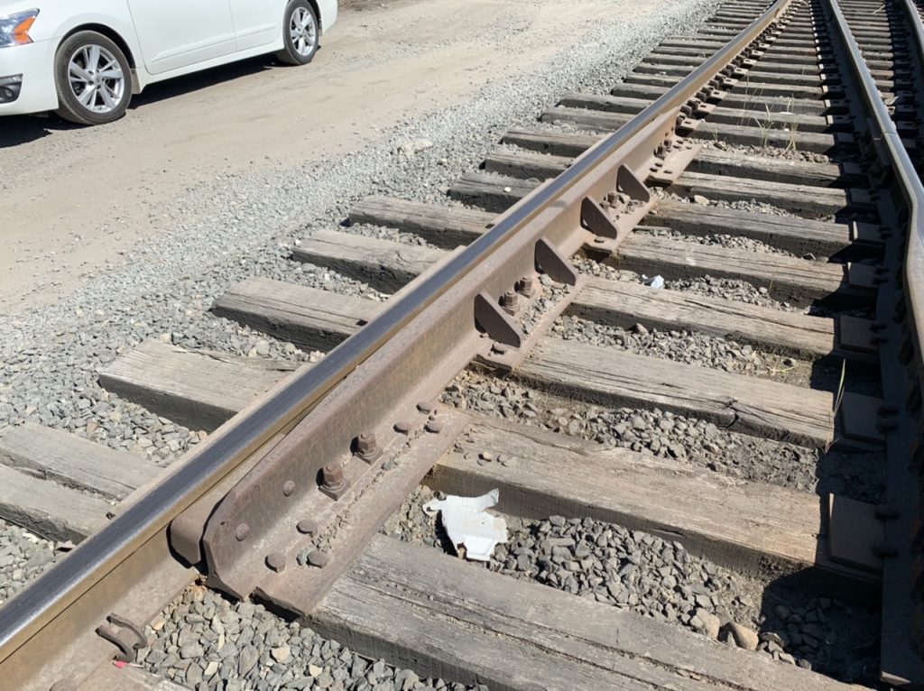
However, there are also guard rails that do not use braced guard rails. I often find this type of turnout construction in industrial areas because the tracks have not been upgraded in years.
So ultimately my question to you is do you want me to install the rail braces to the guard rails (like I did on my turnout) or leave the off?
My suggestion for these #6 turnouts leave the rail braces off of the guard rails. We can see how they will look on the #8s and make a decision when we get to those.
June 7, 2022
I totally dissembled the rails from the PCB ties to clean the parts and began painting the rails.
My preparation steps.
- Wire brush in a rotary tool.
- Fine and extra fine sanding sticks
- Cotton swab with acetone
- Rinse with alcohol
June 8, 2022
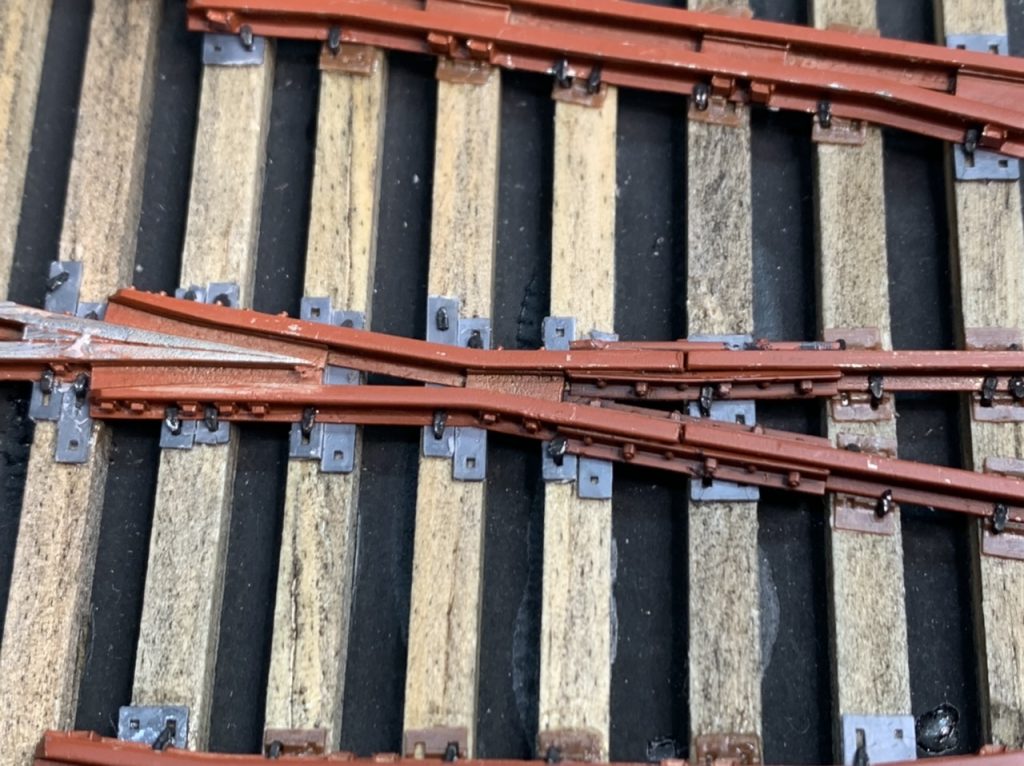
I started spiking the #6 Left turnout today. I got the straight stock rail, the frog and the straight closure rail set and mostly spiked.
June 11, 2022
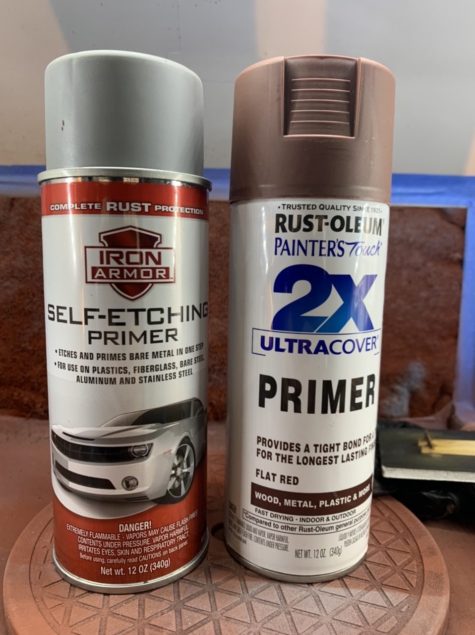
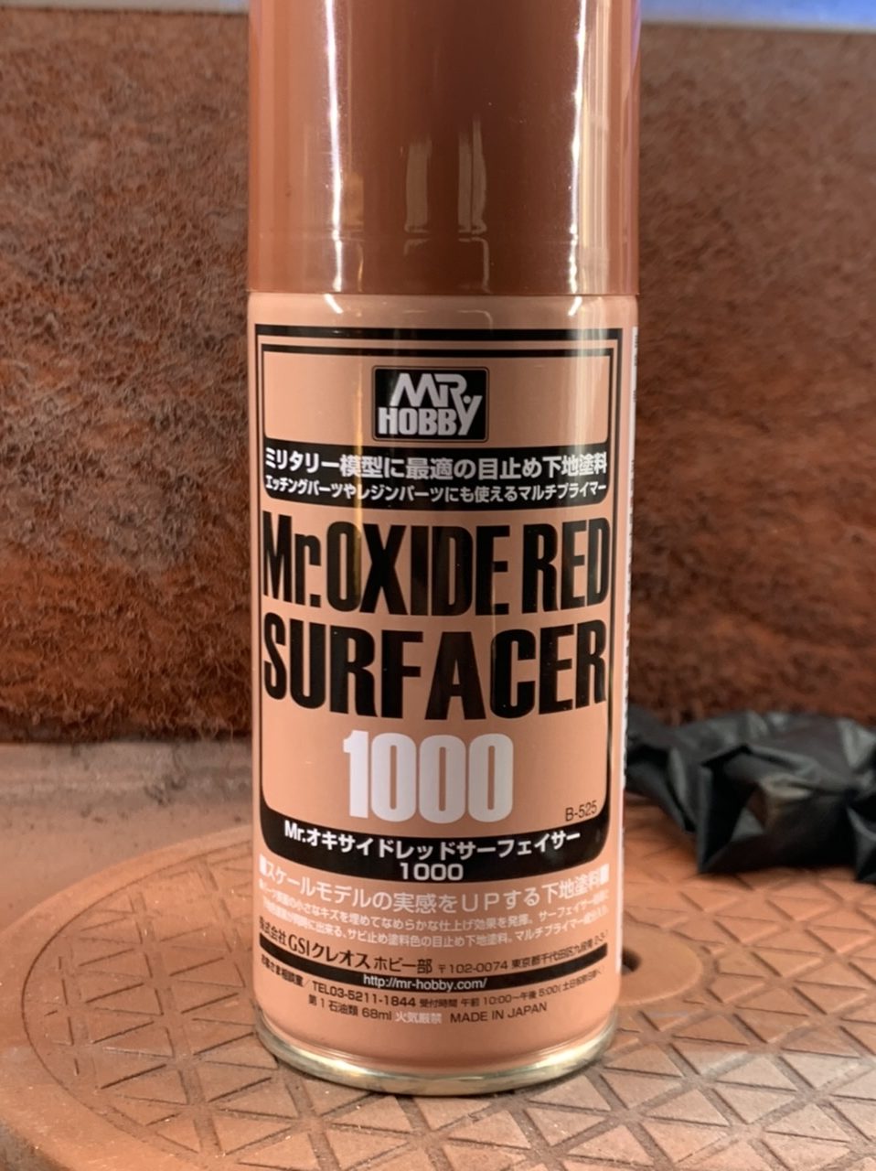
I was dissatisfied with the performance of the primer I used on the rails. The primer was chipping too easily. This last couple of days I removed the rails, stripped them and primed them with a different primer. I’m much more satisfied with this new primer and continued to spike the rails to the #6 Left turnout.
June 12, 2022
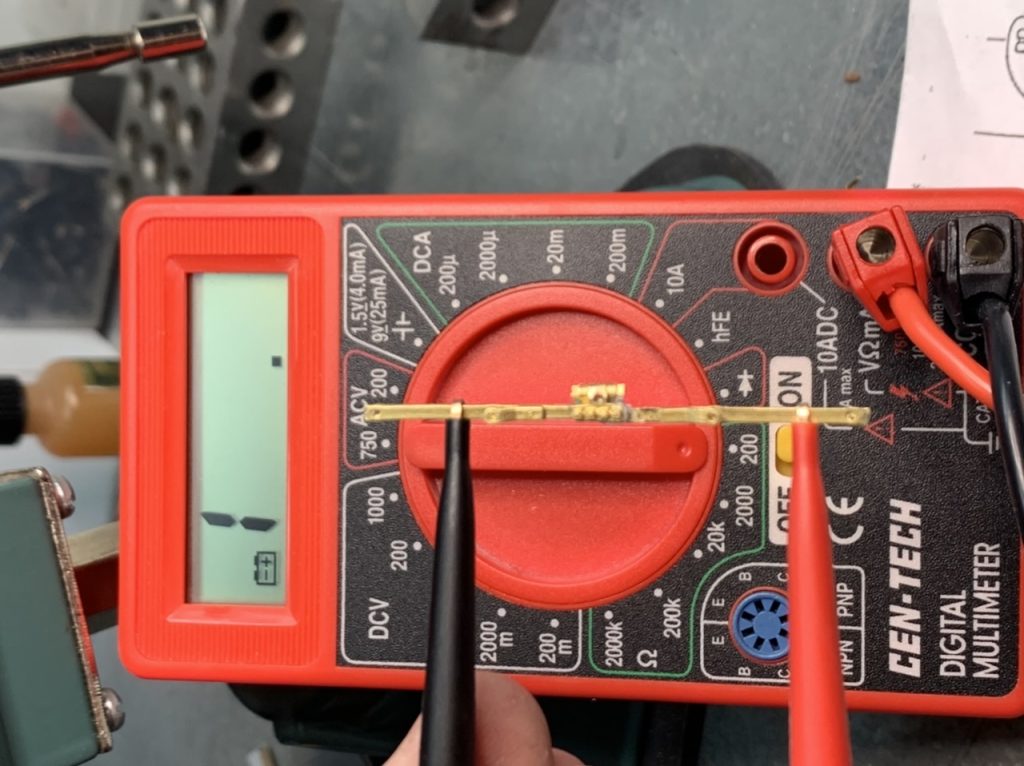
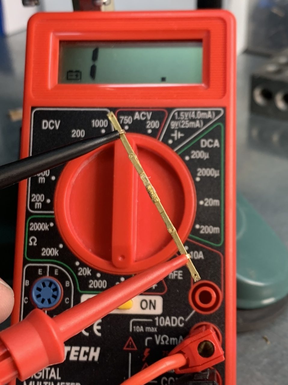
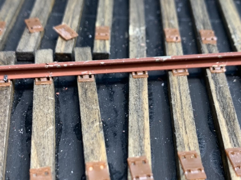
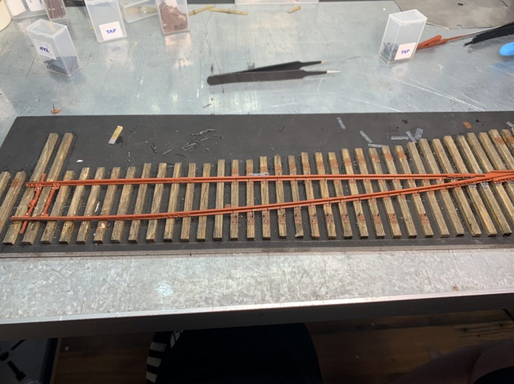
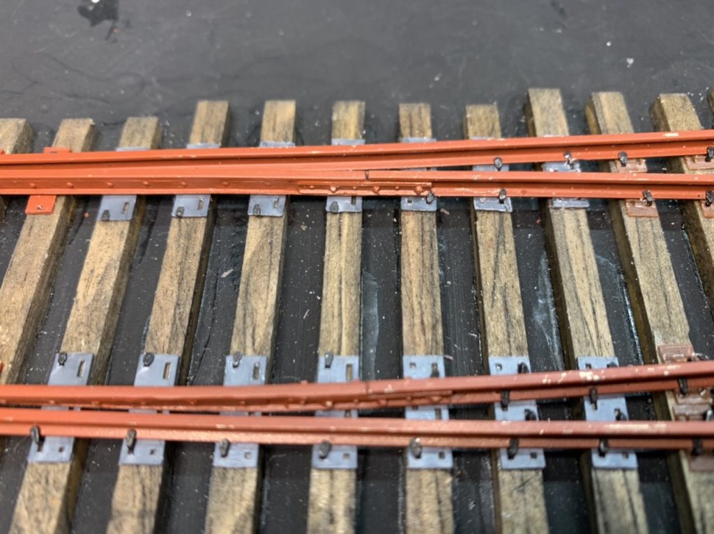
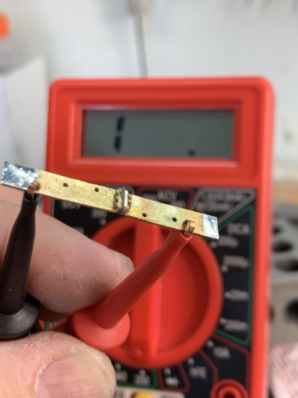
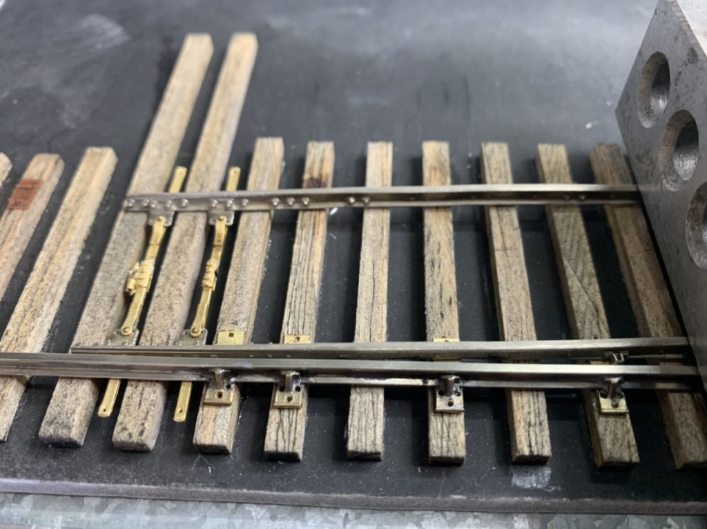
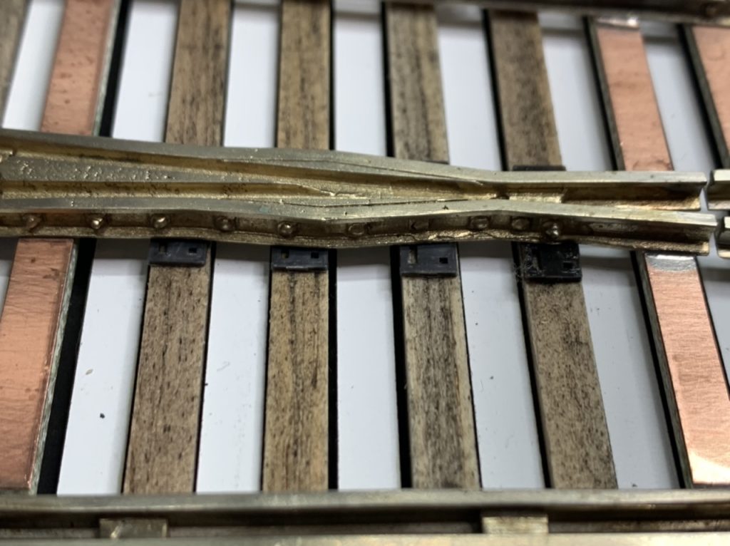
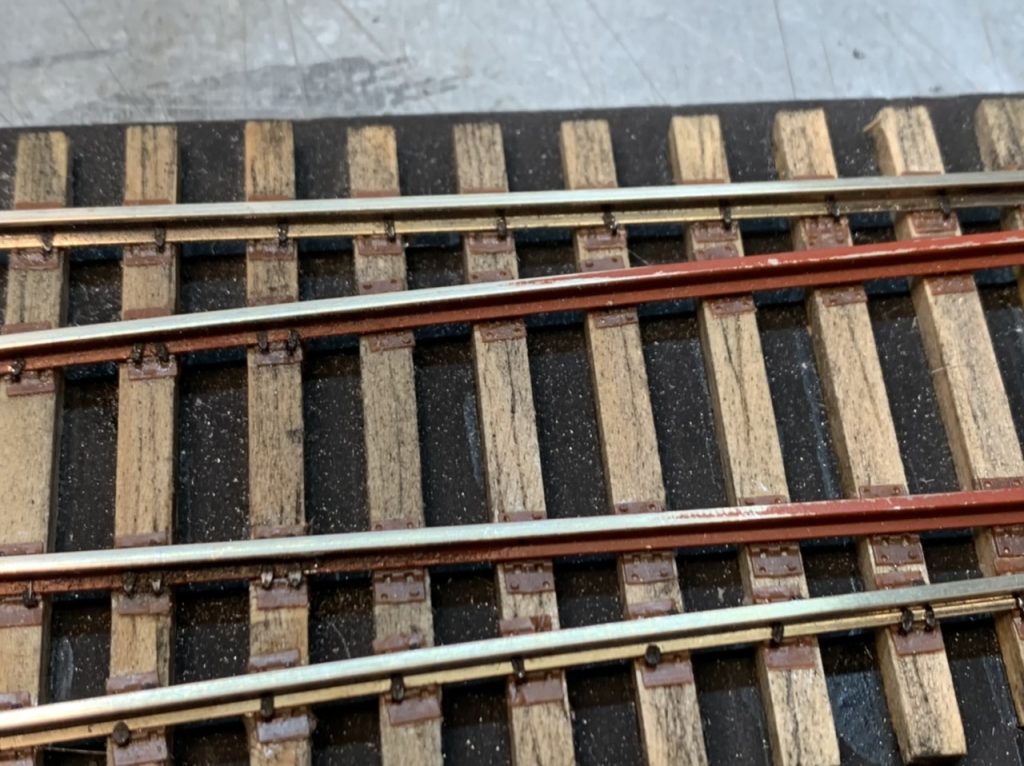
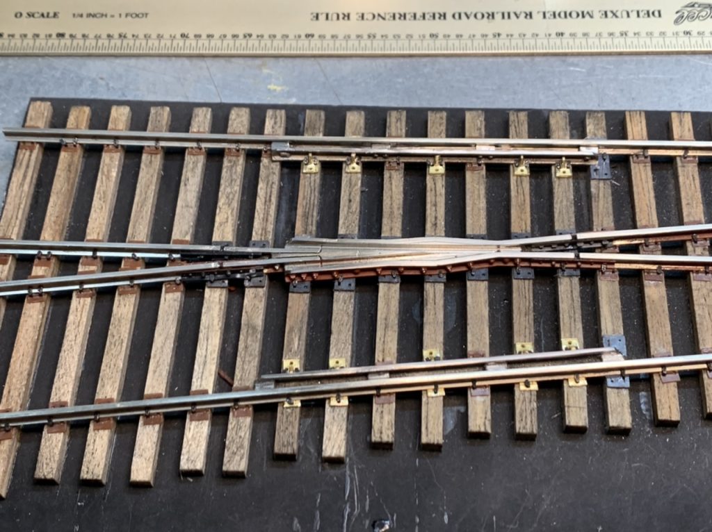
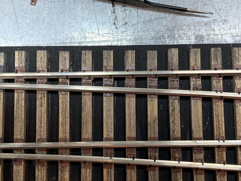
I installed the remaining tie plates and finished spiking the #6 Left turnout today. I did an electrical test for shorts, both sides are isolated, the frog is isolated and the frog rails are isolated.
I started working on the #6 Right turnout. I removed the throw bars, corrected the gauge at the frog, placed tie plates and soldered the rail braces.
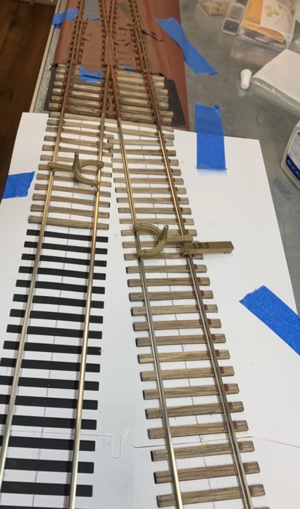
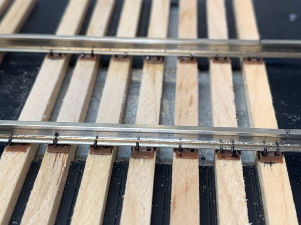
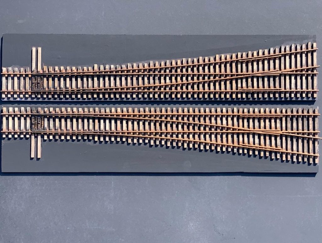
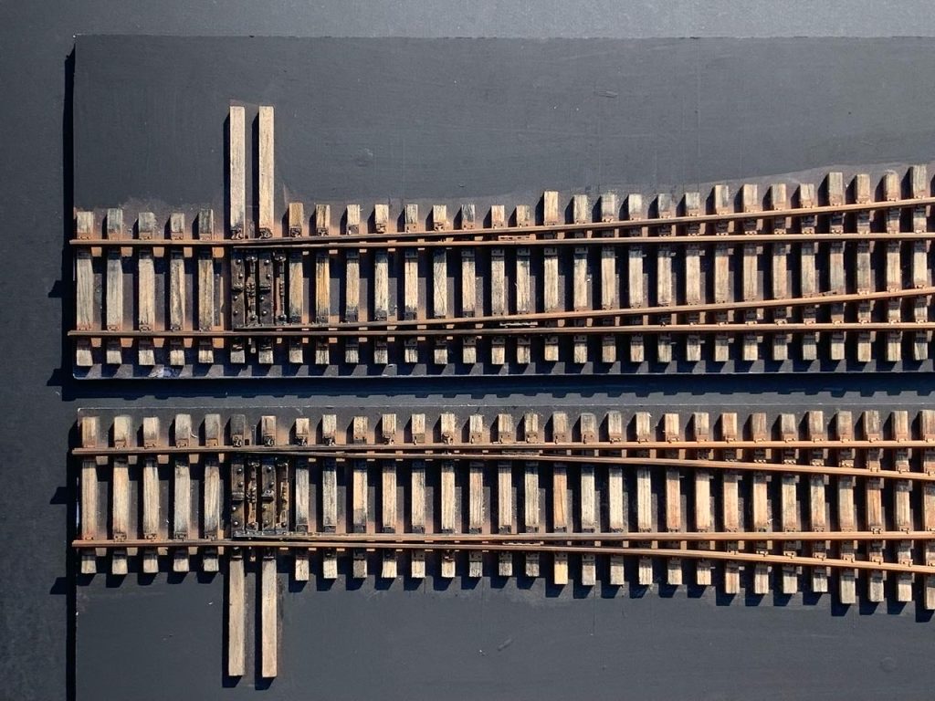
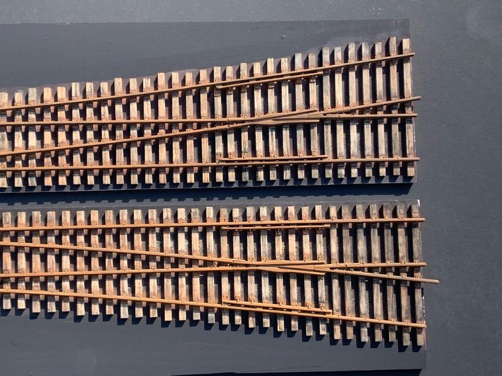
#6 Left
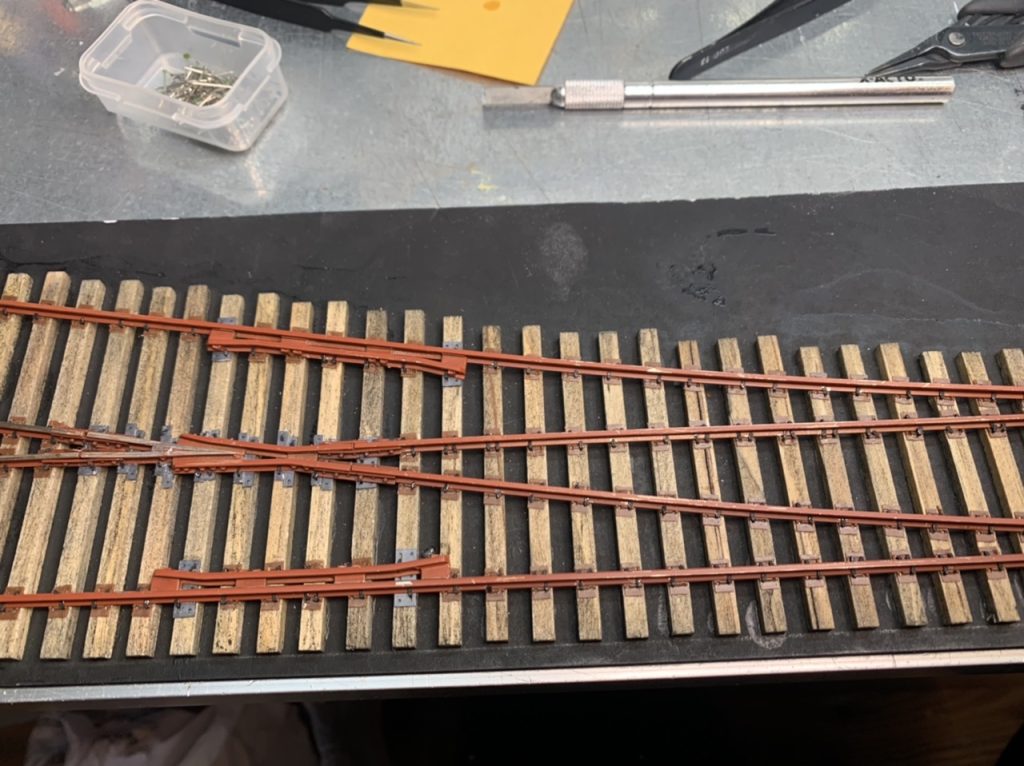
#6 Right
Since the gauge problems with this turnout were minor, I should be able to install it as one piece (instead of totally disassembling it before spiking it to the ties). I’ll prime the rail after it is in place.
June 16, 2022
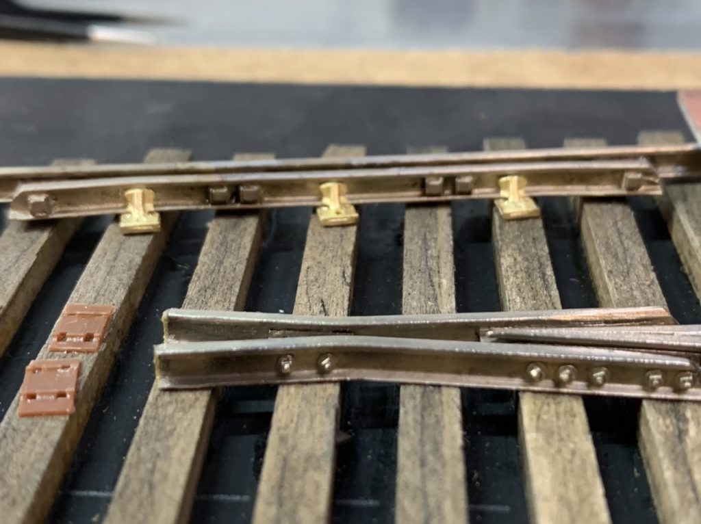
I continued work on the #6 right turnout. Placed the frog plates & the slide plates.
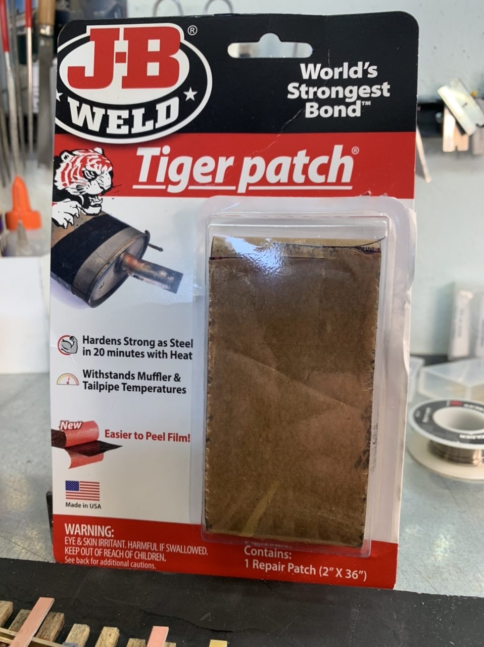
The gauge plate bond has been bothering me. I have been using CA, but it produces a weak and heat sensitive bond. I found a new product: JB Weld Tiger Patch. It is a high heat epoxy tape that does not conduct electricity. It produces a very strong bond and I can solder the gauge plates to the rail without damaging the bond. I am using it for the #6 right turnout.
I decided to disassemble this turnout as well. I was thinking I would install the built turnout kit to the ties and then clean and paint it. But the more I thought about that plan, the less I liked it. I didn’t think I would be able to insulate the frog and I was worried I wouldn’t be able to clean the rails without damaging the ties or tie plates. So I’ve started disassembly.
June 17, 2022
I cleaned the rails, primed the rails and spiked the #6 turnout.
June 18, 2022
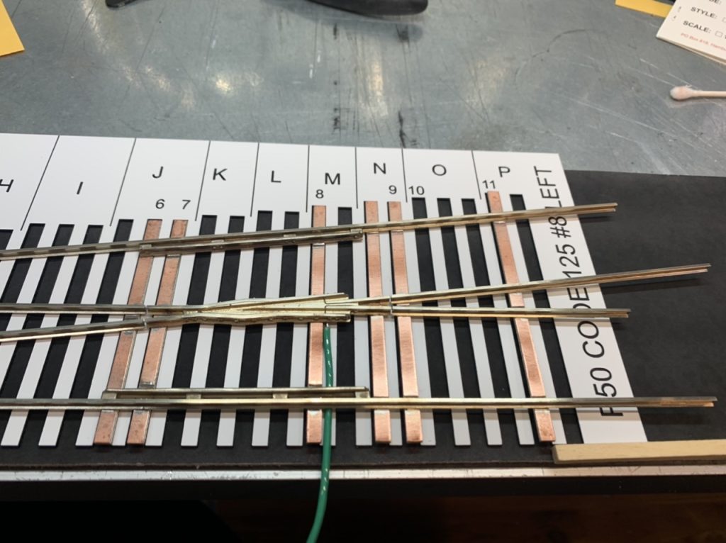
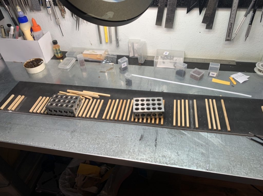
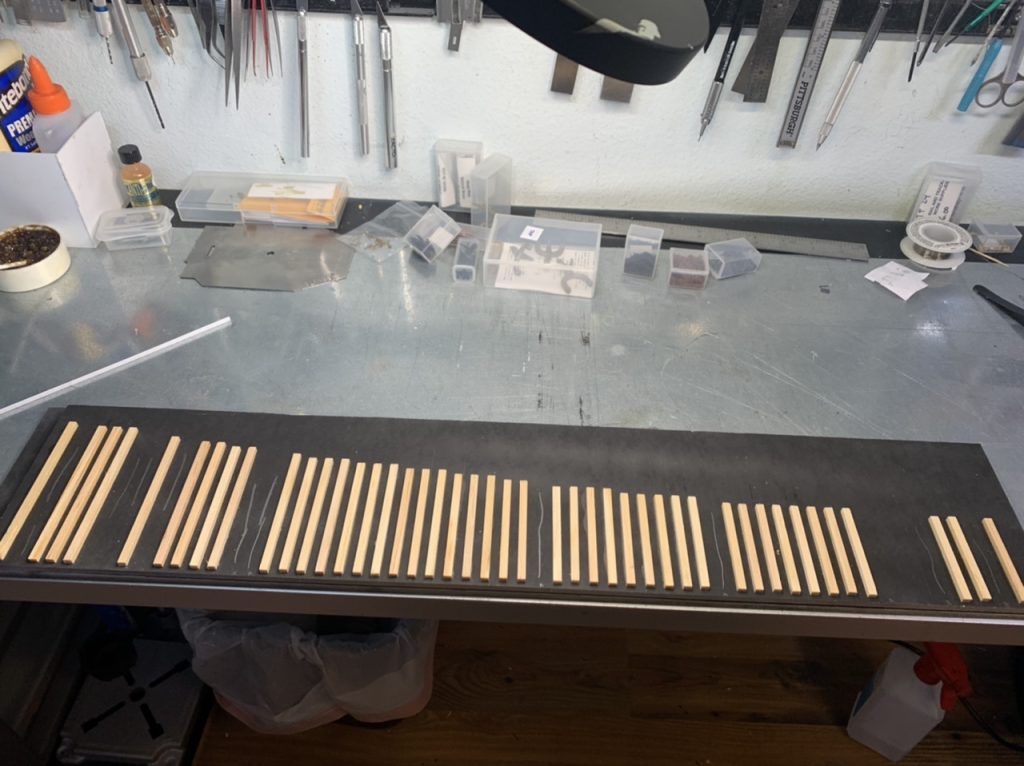
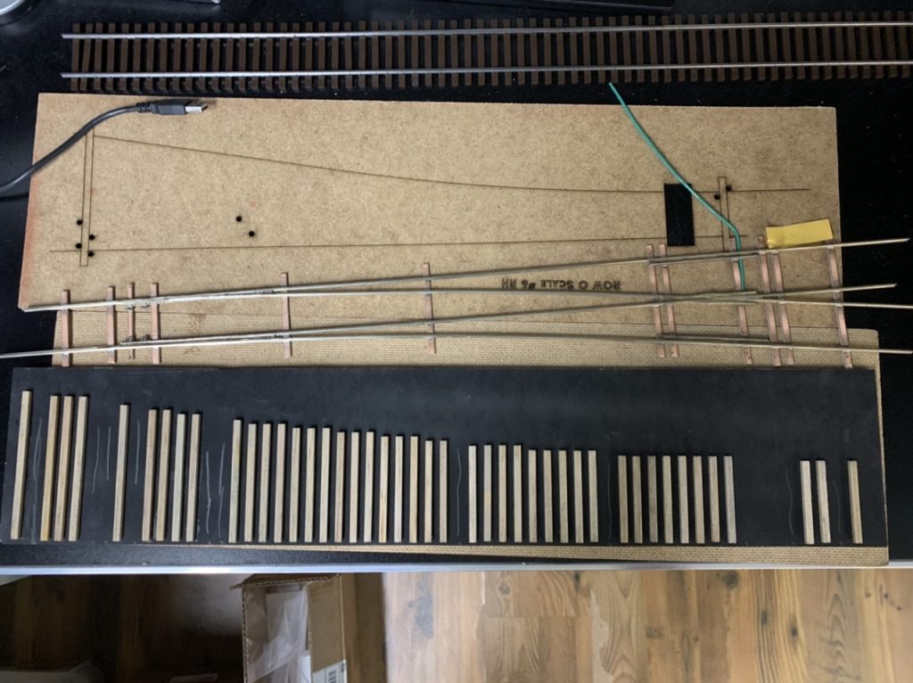
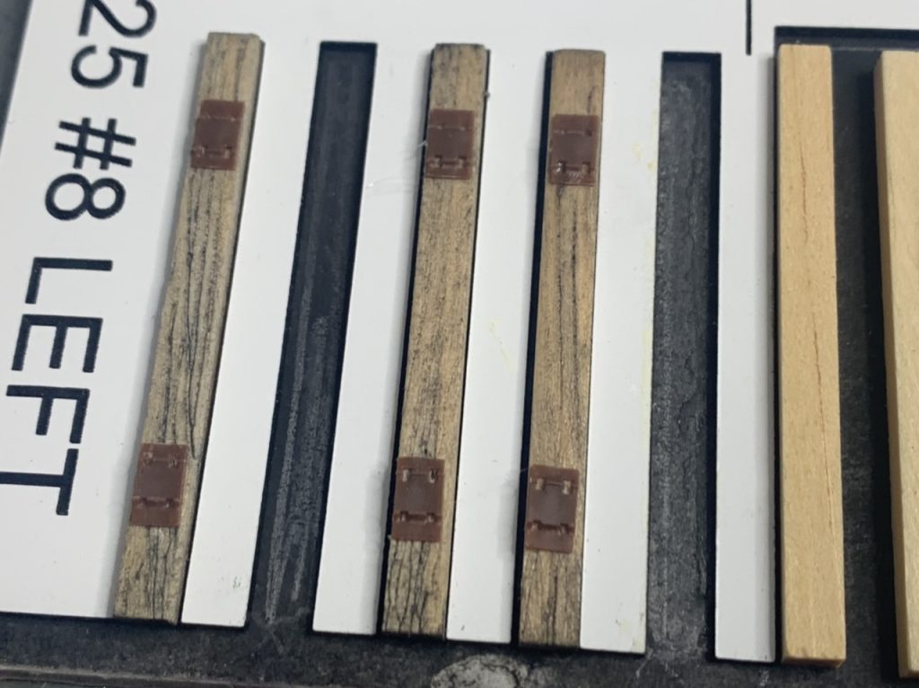
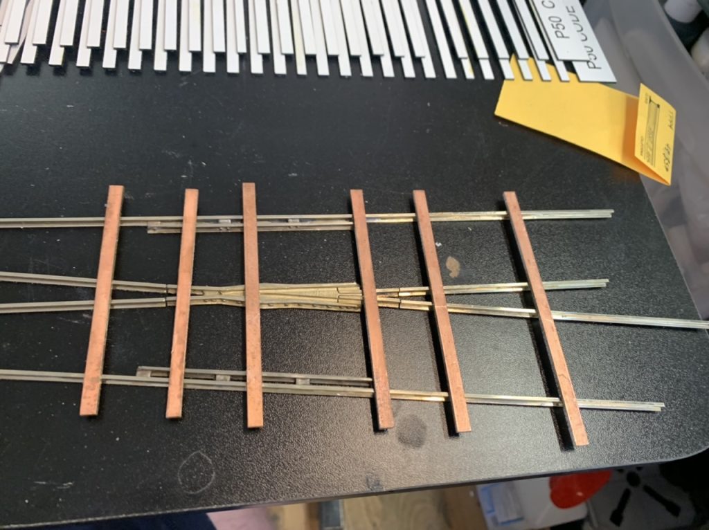
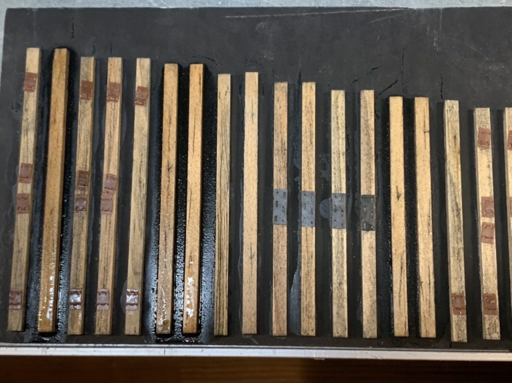
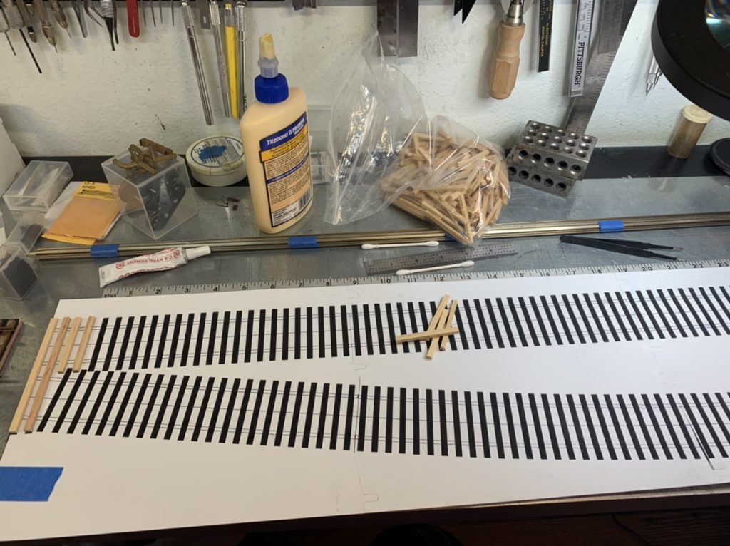
I began gluing ties for the #8 left turnout. Since these turnout kits have the PCB ties soldered to the bottom of the rails, I will approach this this build a little differently. Still trying to decide on a best approach. I also cut some more large tie plates and joint bars from the sprue.
June 20, 2022
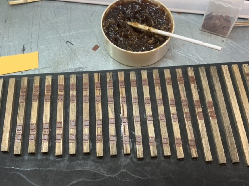
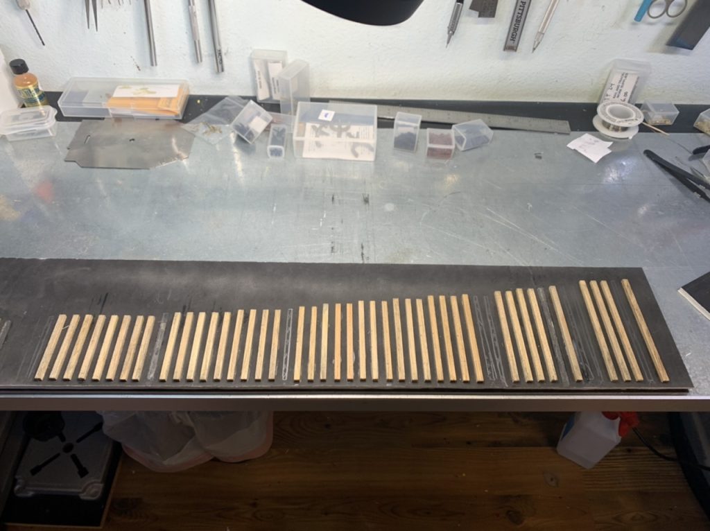
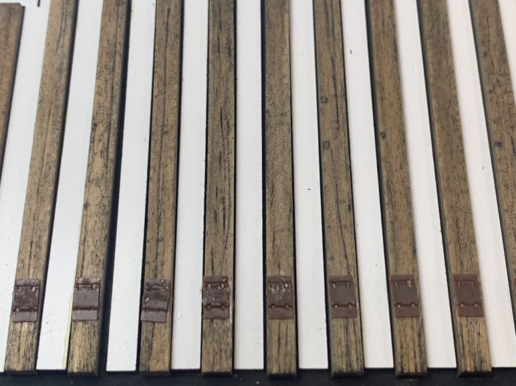
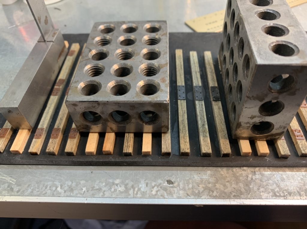
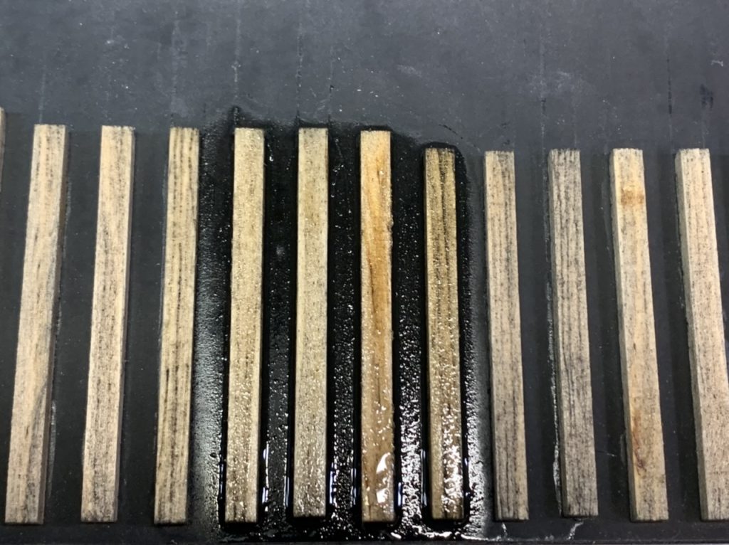
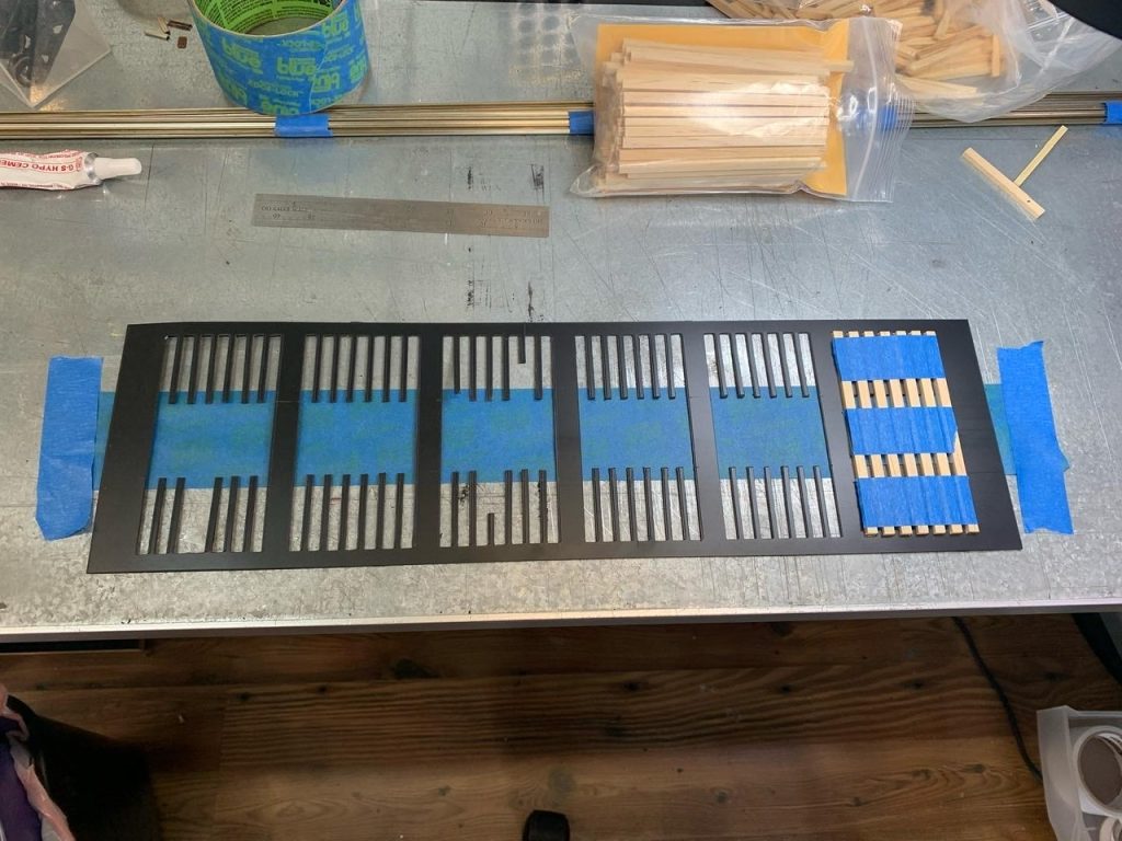
I sanded the #8 Left turnout and began to stain it. I started gluing ties for the #8 Right turnout.
June 21, 2002
I worked on ties for both the #8 turnouts.
June 28, 2022
I continued to work on the #8 turnouts. Staining the #8 right and started tie plates for the #8 left.
July 8, 2002
I am continuing work on the #8 Left turnout. I removed the frog wire; disassembled the rails from the PCB ties; added throw bars; glued, sanded and stained the missing wood ties; added some of the rail braces; & worked on insulating the frog.
July 11, 2022
I primed the frog, frog rails and closure rails/point rails. I started laying tie plates on the #8 right turnout.
June 12, 2022
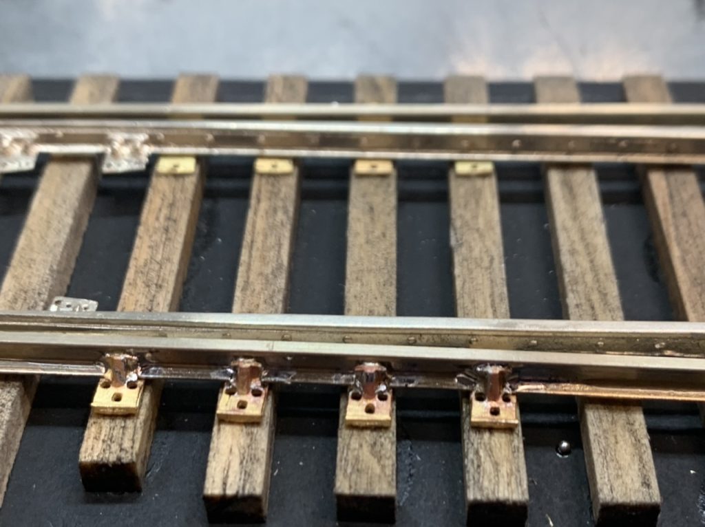
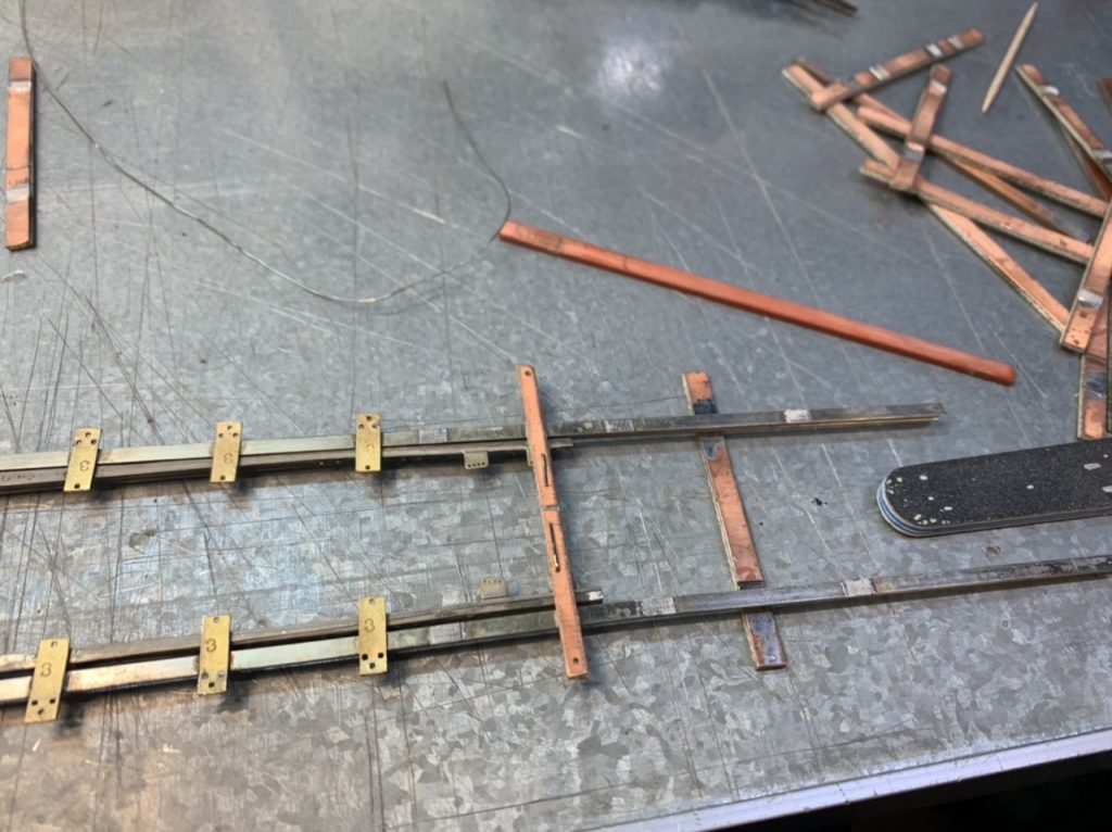
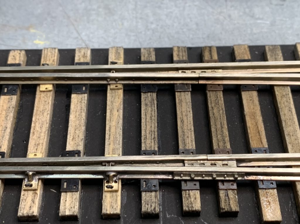
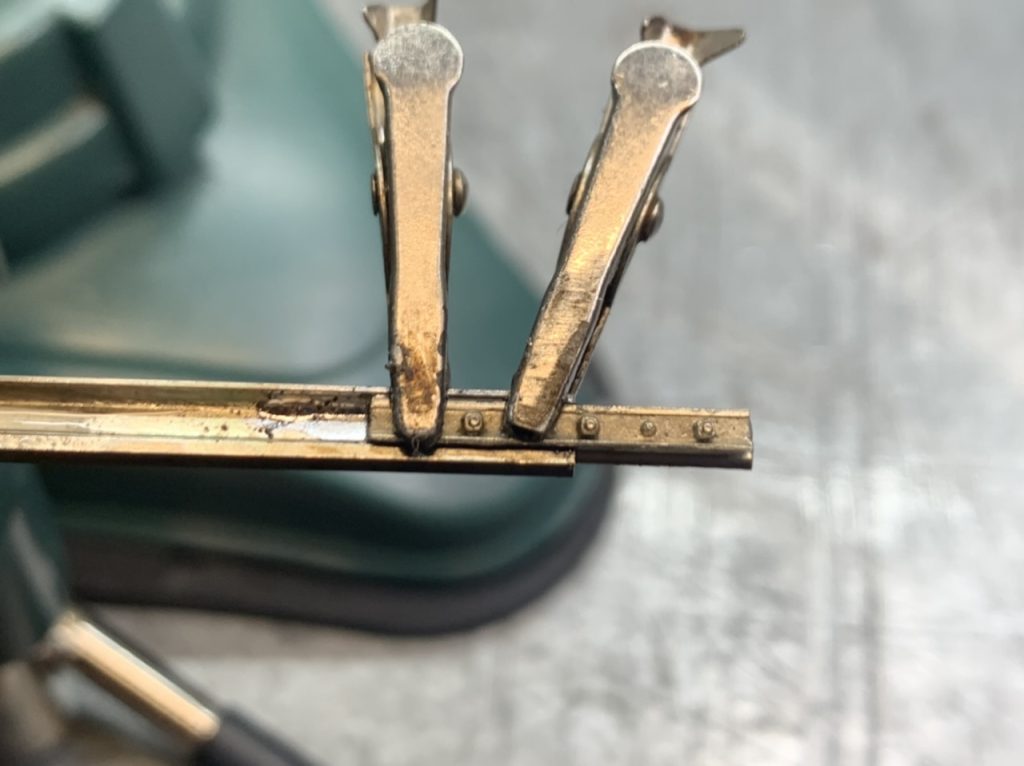
I worked on the castings for the #8 right turnout. Soldered the rail braces, soldered joint bars to correspond with the heel blocks, soldered the guard rails to the stock rails. Then filed and sanded to clean the excess solder.
July 18, 2022
I am working on the #8 left turnout again.
July 23, 2022
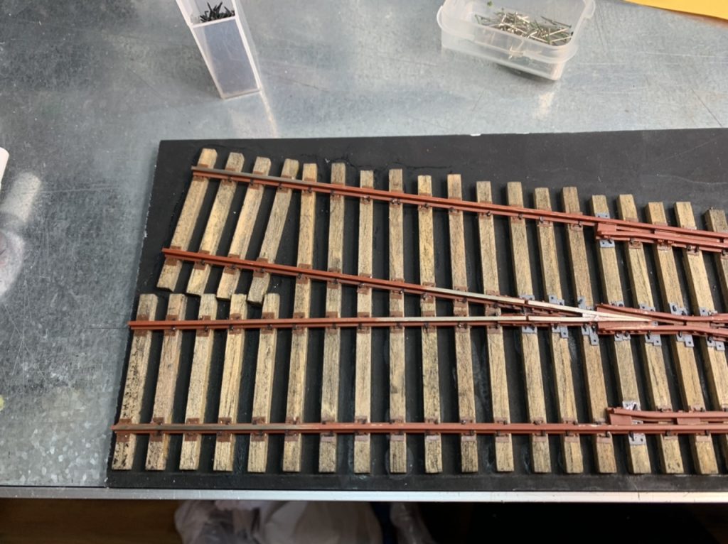
I have continued to work on the #8 Left turnout. Completing the tie plates, guard rail braces and spiking the rails.
August 1, 2022
I completed the #8 left turnout today.

August 2, 2022
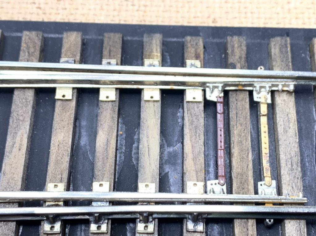
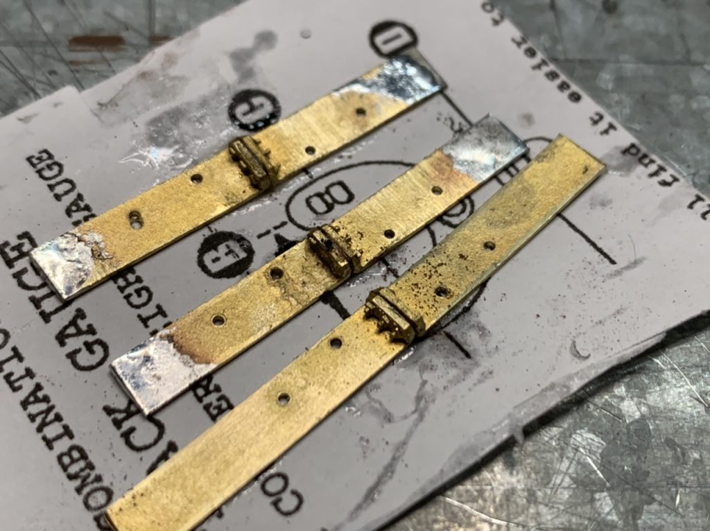
I am working on the #8 right turnout. I unsoldered the PCB ties from the bottom of the rails and soldered PCB ties to the top of the rails. I’m trying this method to see if I can have less fuss placing the rails. I laid some the remaining wood ties. I started working on the transit clips and throw rods.
August 8, 2022
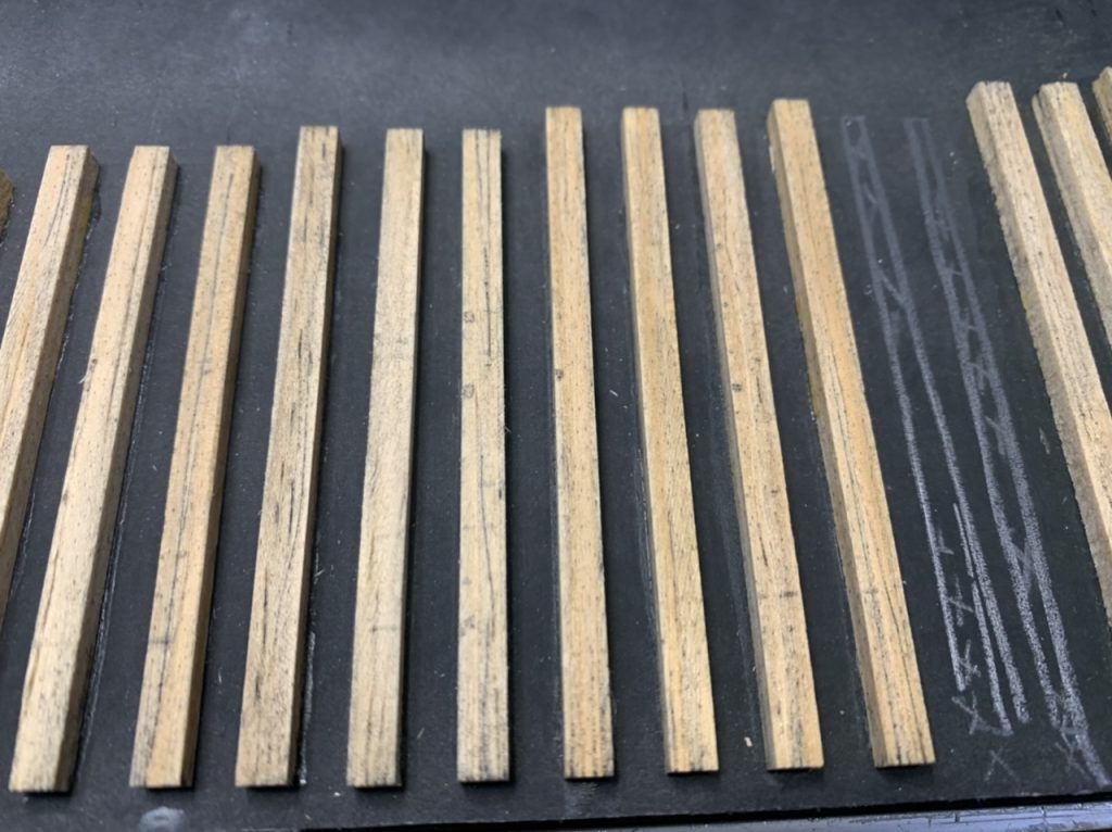
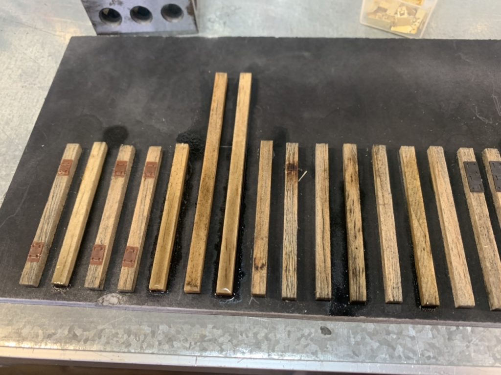
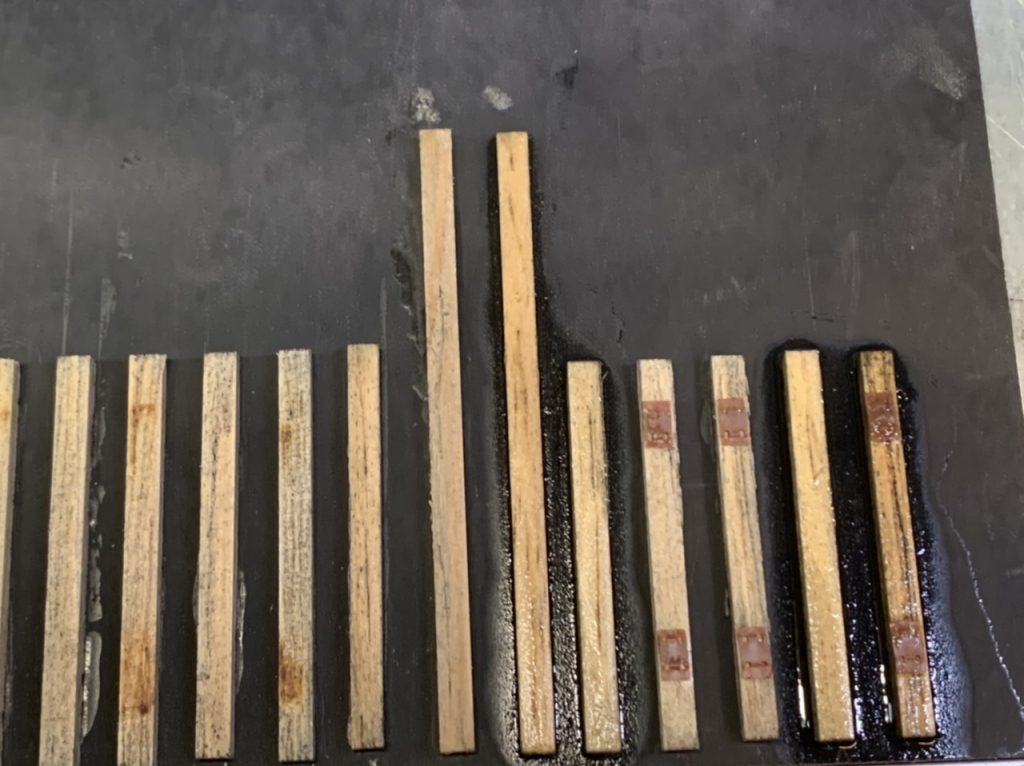
I’m working on the #8 right turnout. I glued the remaining ties into place. Sanded the ties to match the existing ties. Distressed the ties and have added three coats of stain.
August 9, 2022
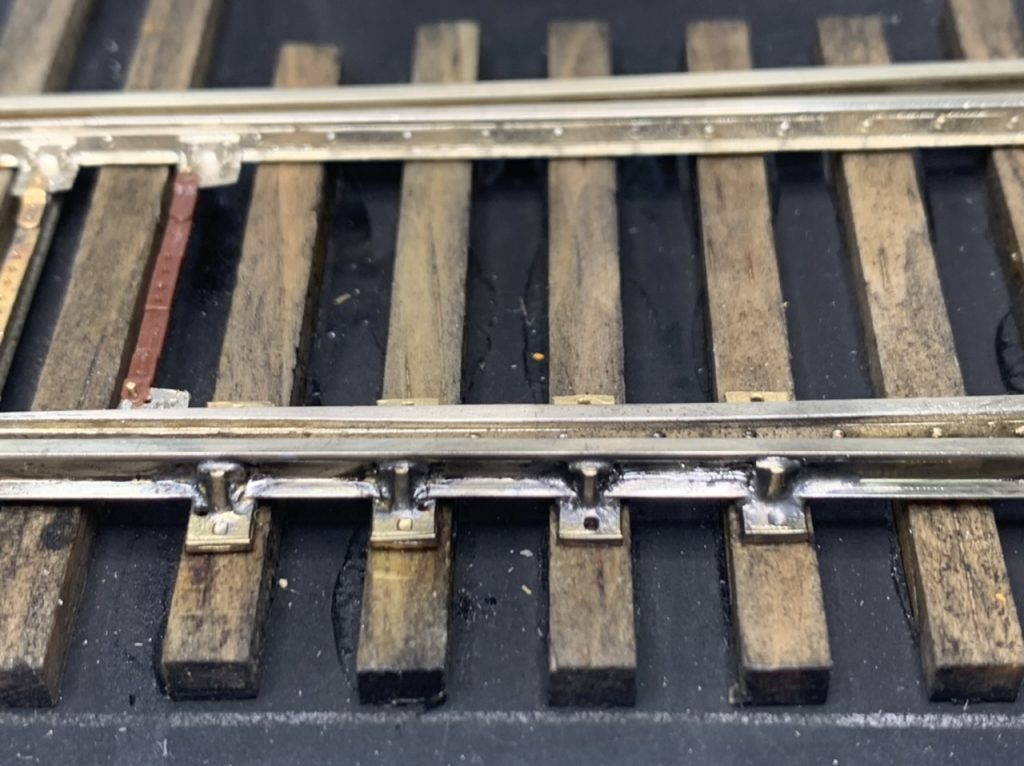
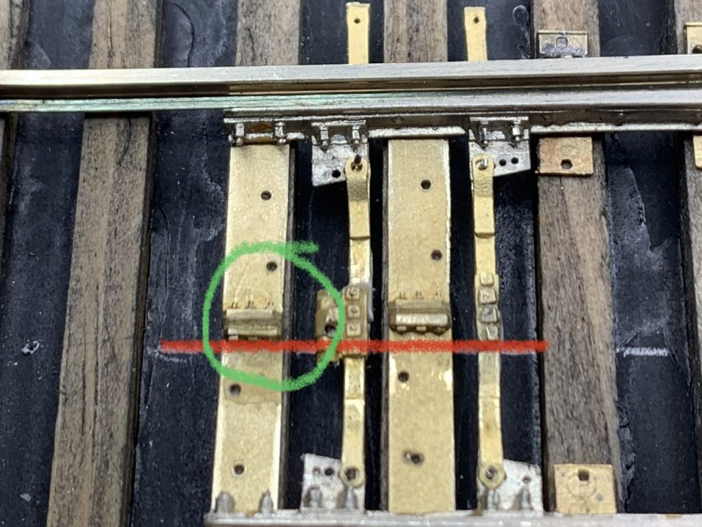
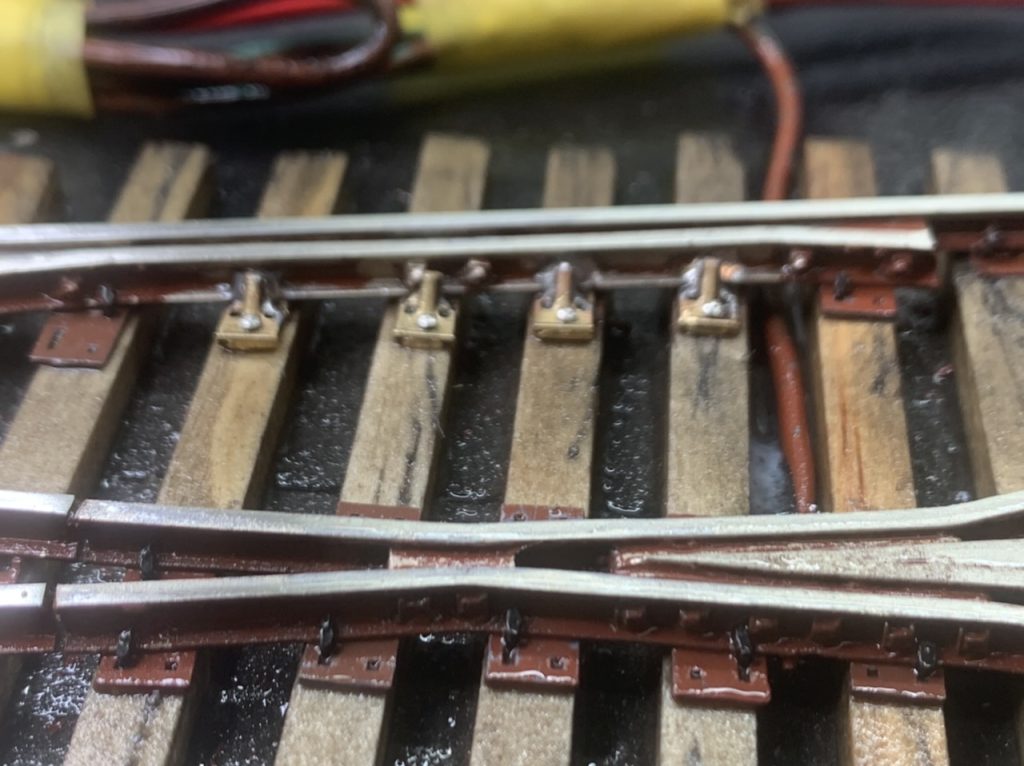
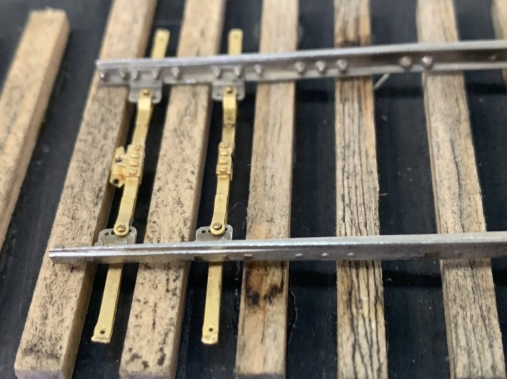
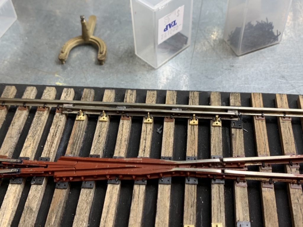
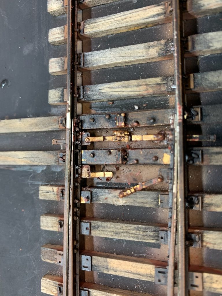
I am working on the #8 right turnout. I added the throw rods, remaining rail braces and gauge plates today.
August 14, 2022
I started spiking the #8 right turnout today. Removed the remaining PCB ties. Started filling in some of the 24” tie plates.
August 18, 2022
I continued spiking the #8 right turnout. Placing the frog and straight side rail and frog rail. I had to file more rail braces for use on the guard rails. Spiked the straight side guard rail braces. Started on the diverging side rails beyond the frog.
August 21, 2022
I am nearing completion of turnout construction. I laid the remaining tie plates beneath the point rails and frog rails. I installed the guard rail braces & gauge plate braces. I installed the joint bars between the frog and adjacent rails. I’ve finished spiking. I will go back over the last turnout soon and make sure everything is complete and correct.
I will move on with painting after the weather cools and there is less humidity.
August 24, 2022
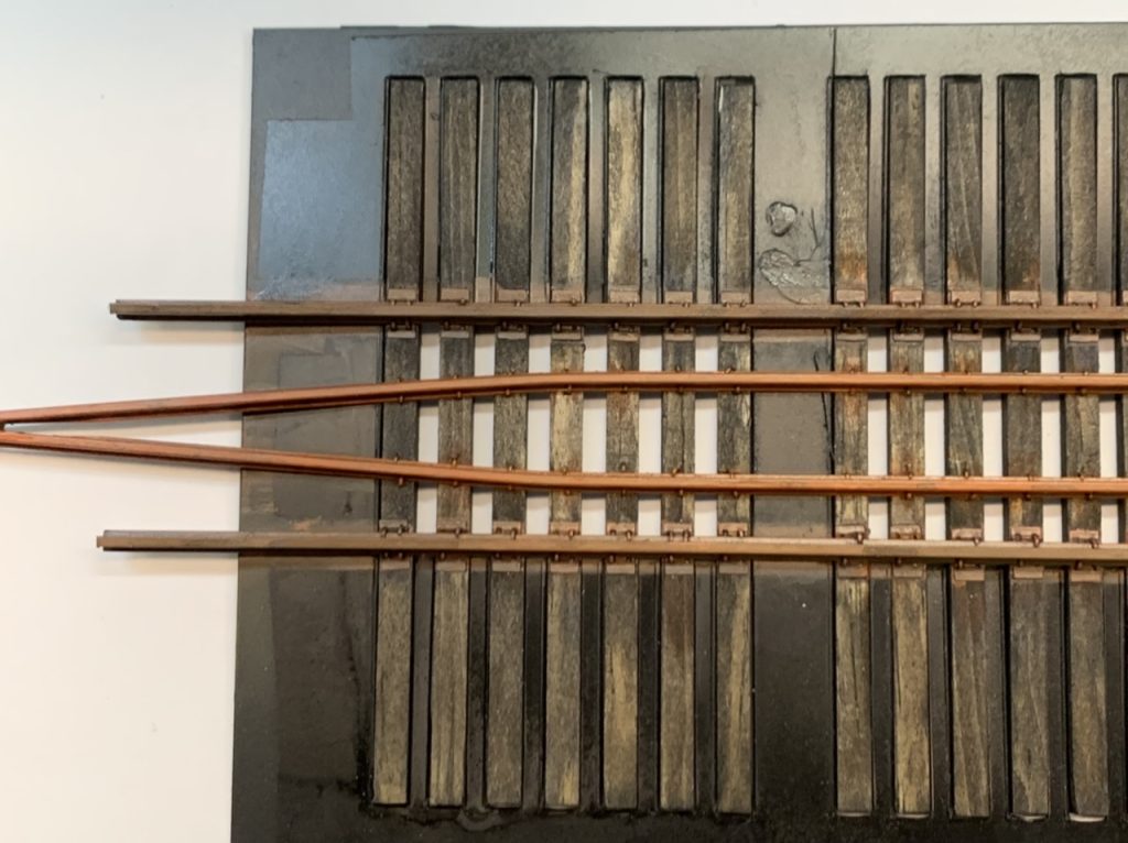
I am designing the diverging route pieces.
August 25, 2022
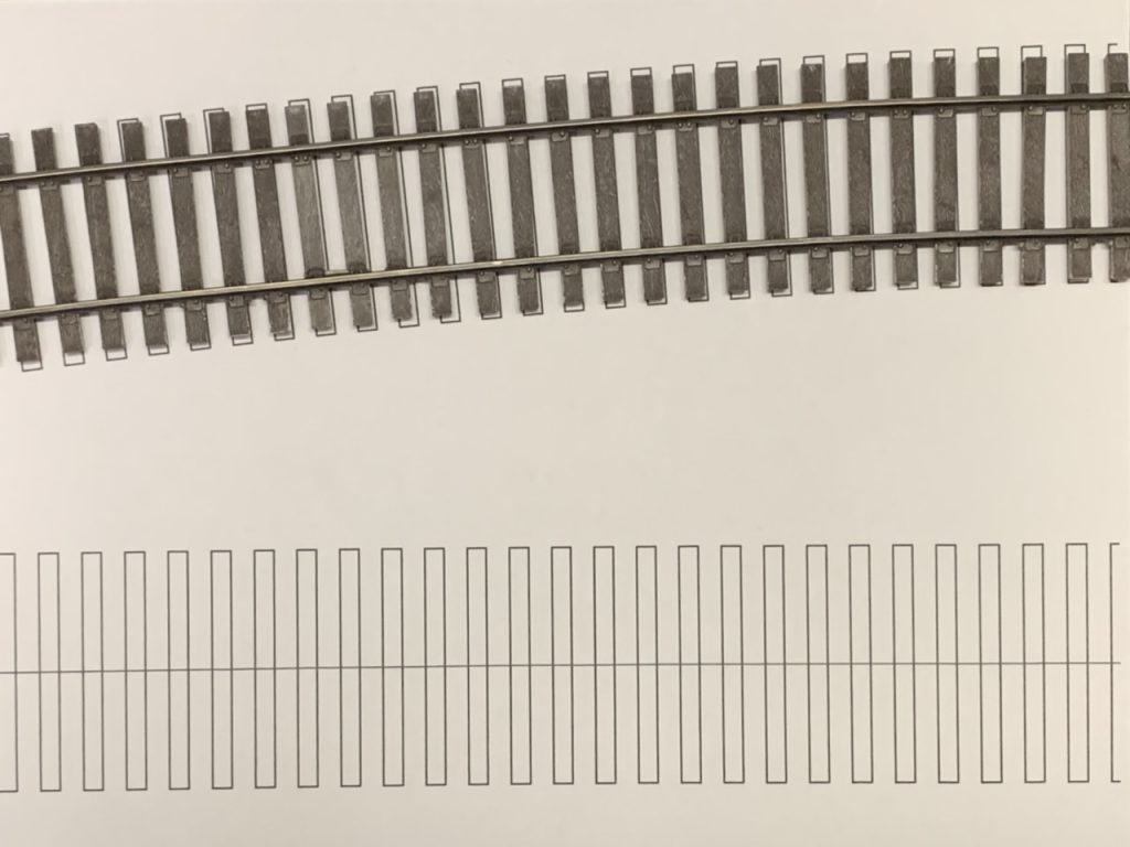
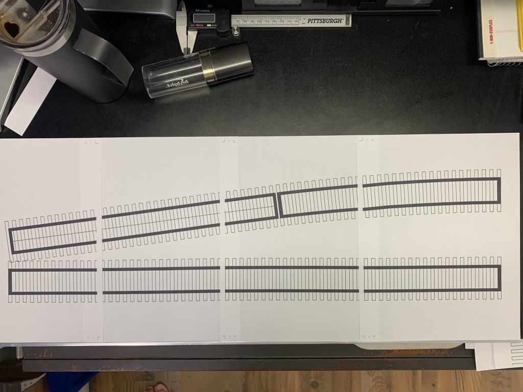
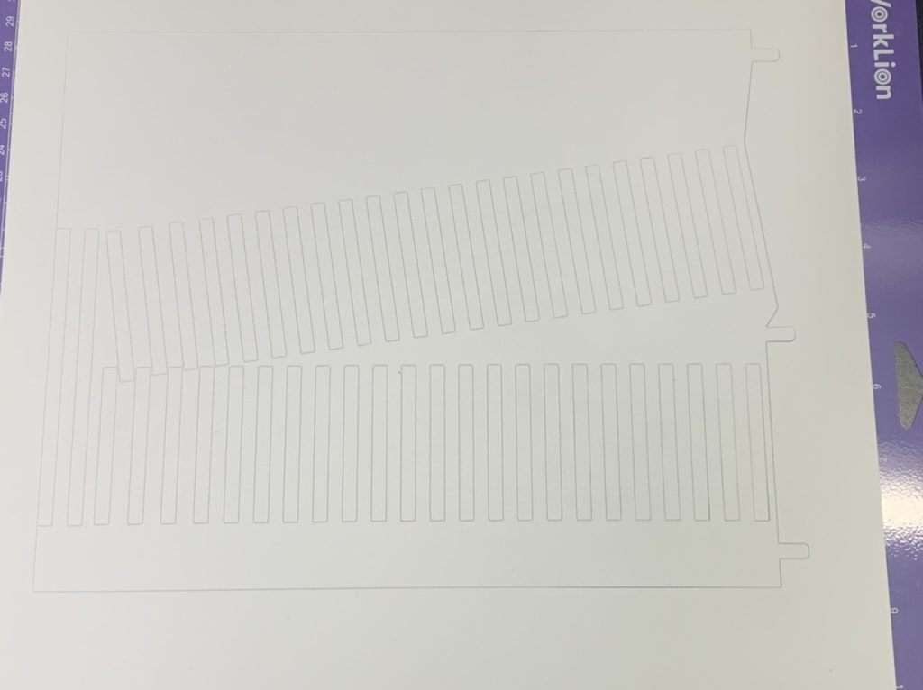
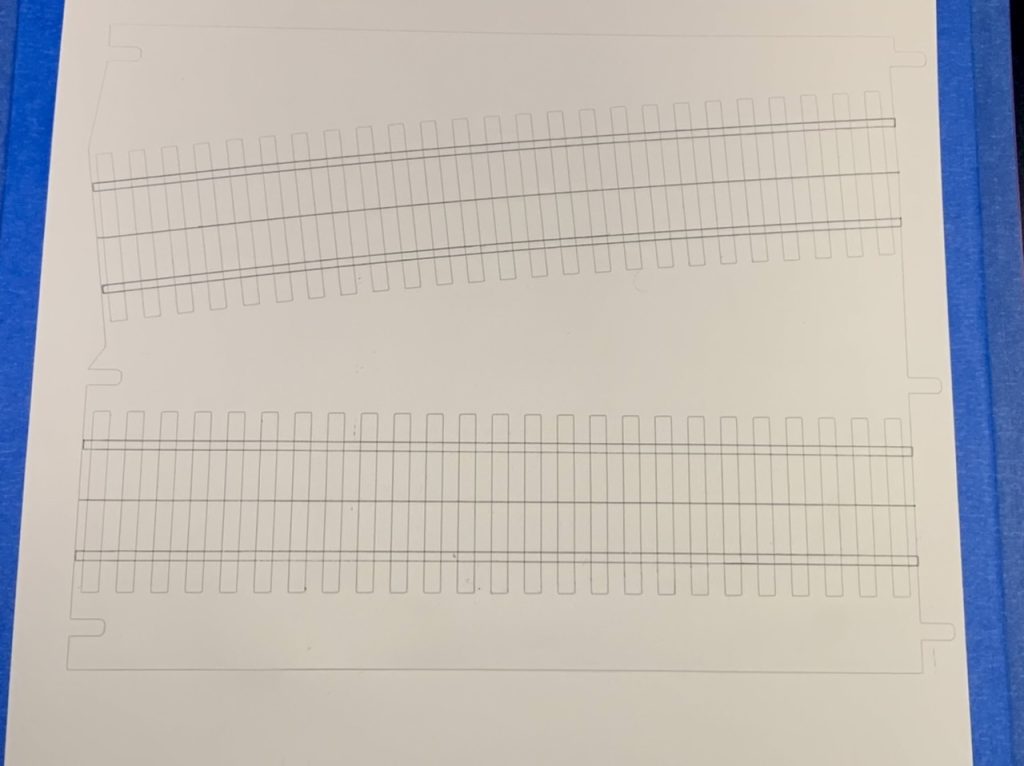
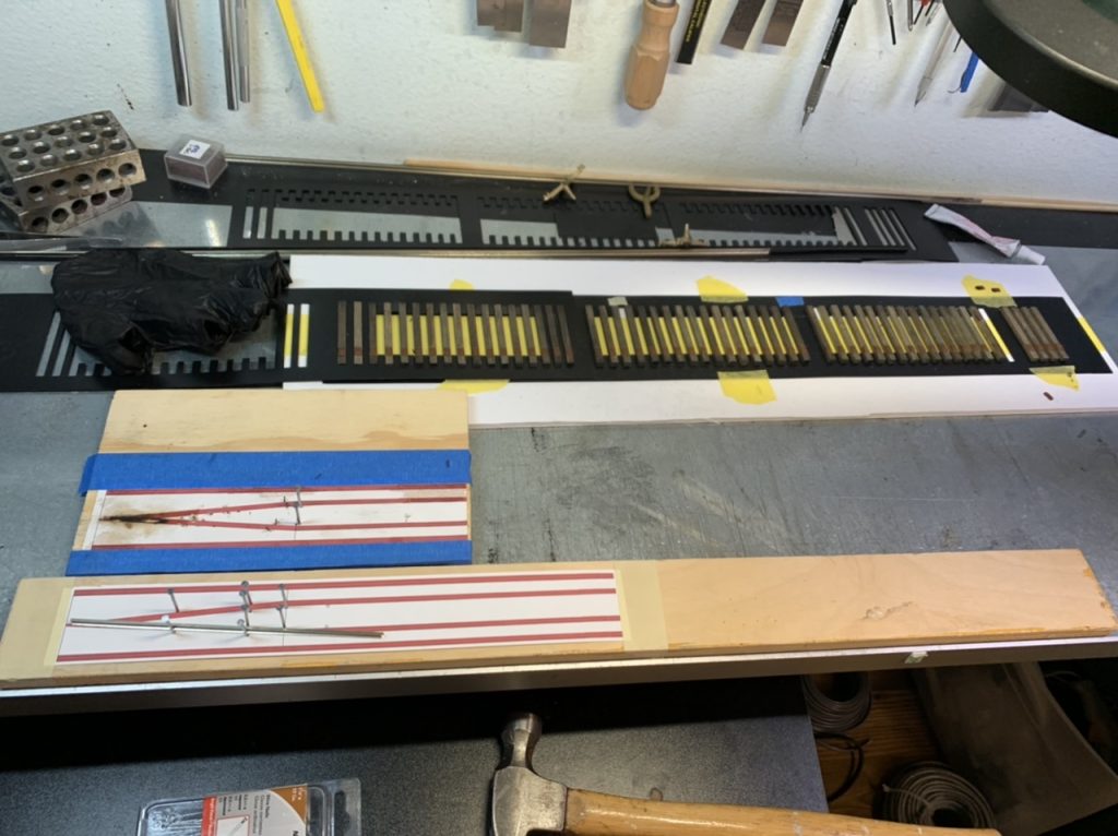
I am continuing to work on the design for the diverging track sections by making full scale drawings.
August 28, 2022
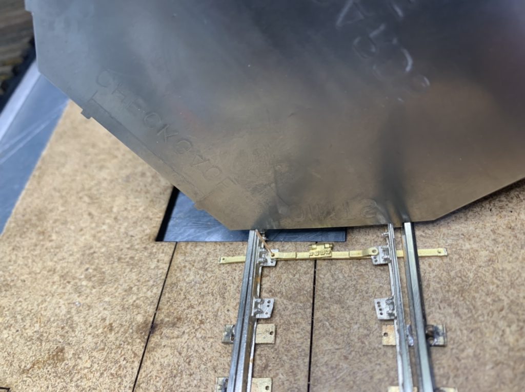
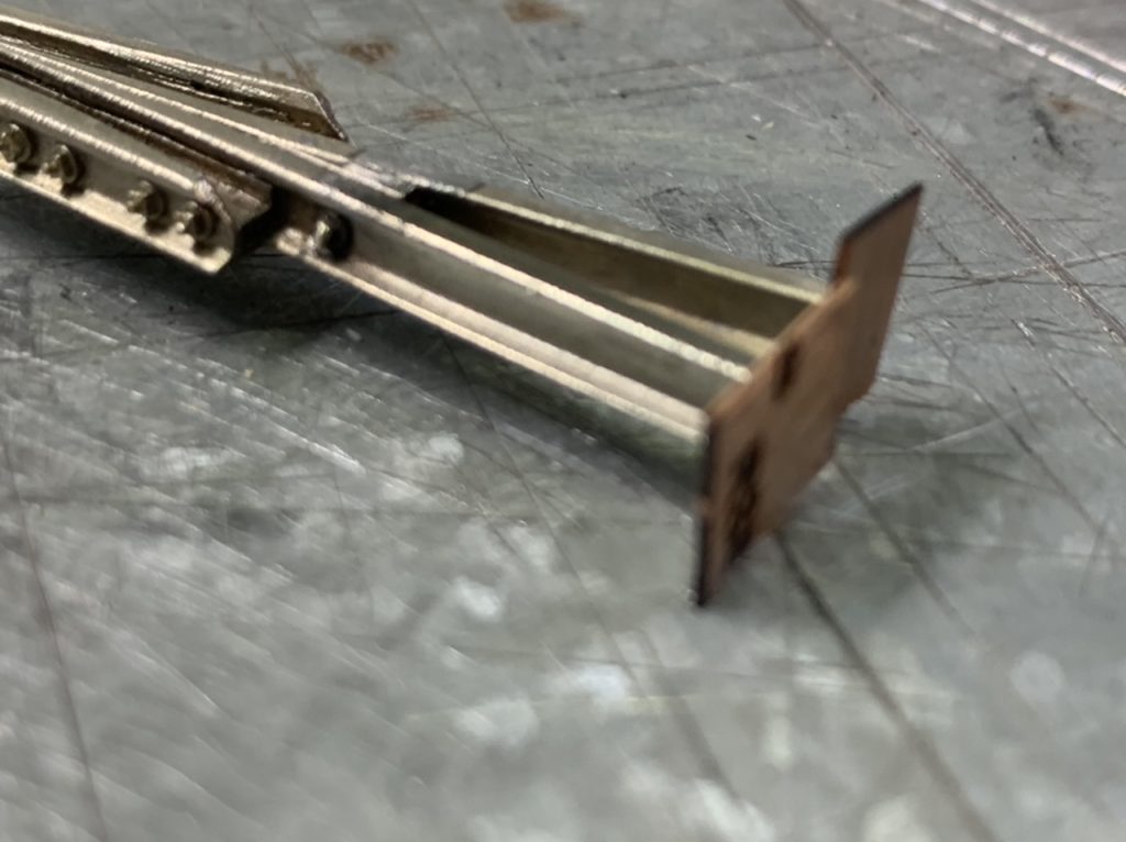
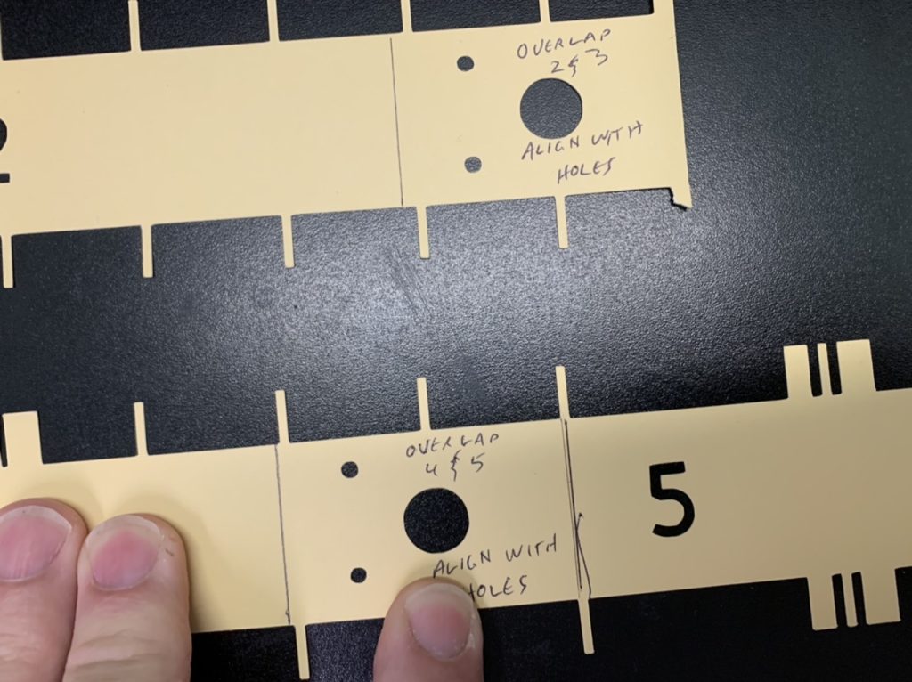
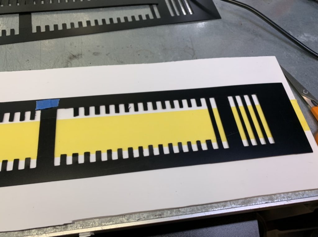
I have continued to work on designs for the diverging track and bridge tracks. I cut bridge track templates and will mail them this week. I also am testing glue for the bridge track sections.
September 15, 2022
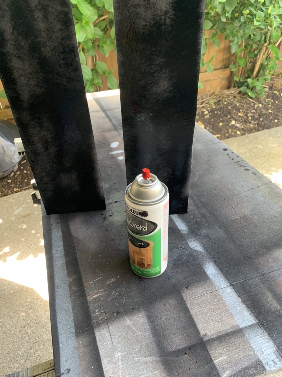
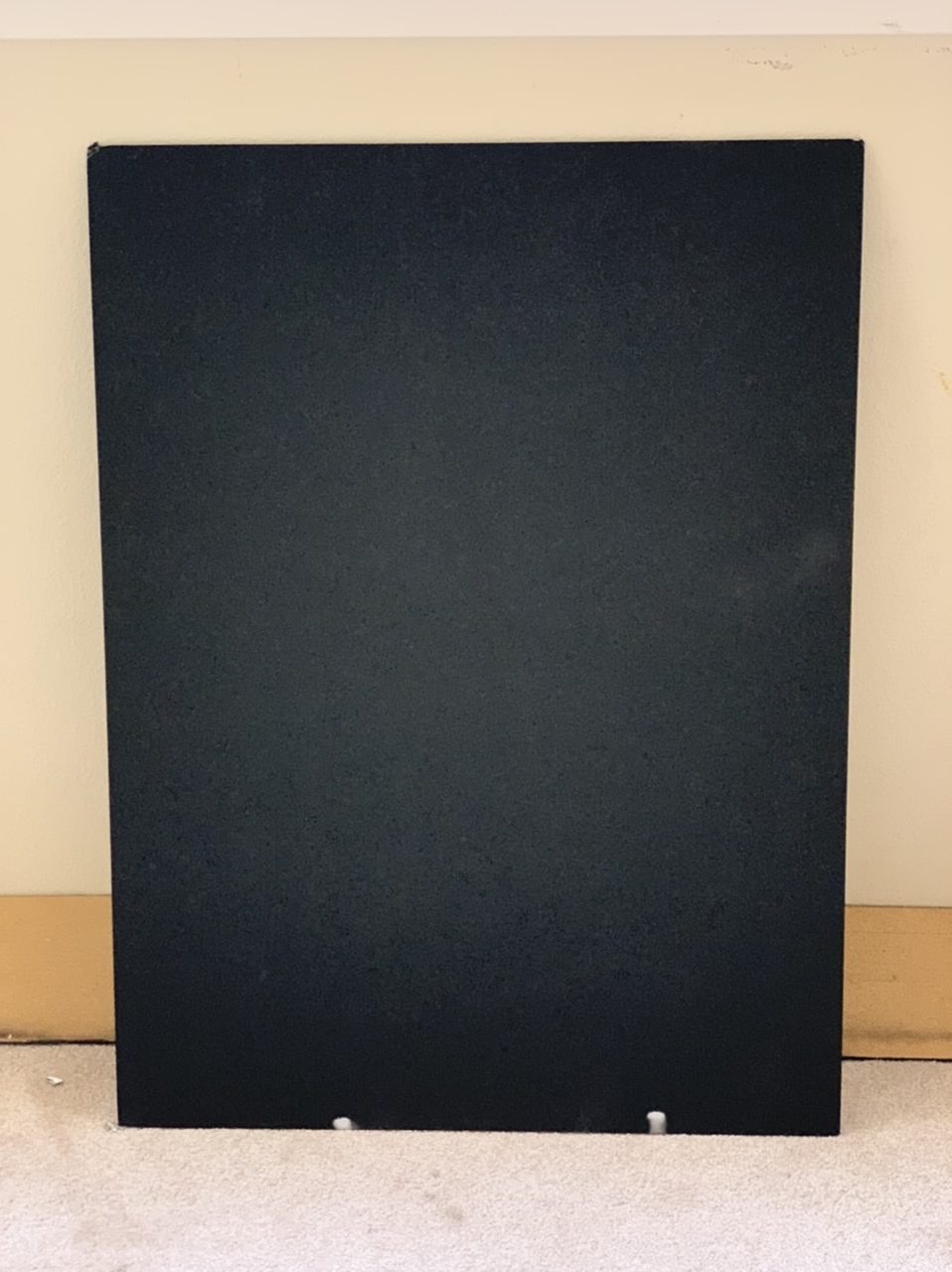
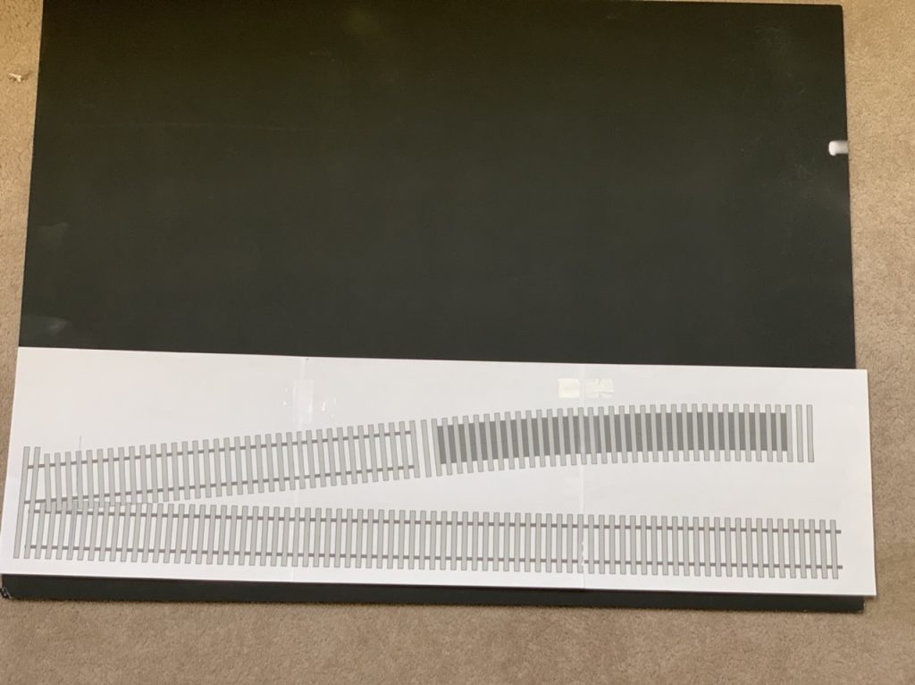
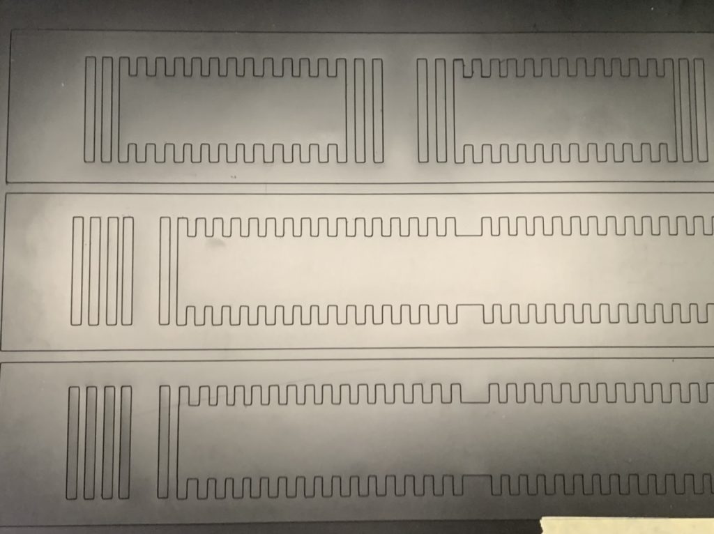
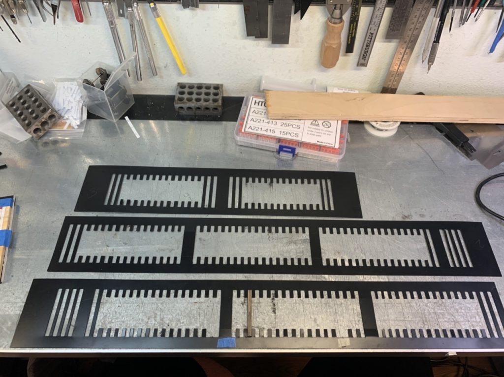
I have ordered supplies from Right-O-Way and started removing tie plates from the sprues. I purchased more gator board to lay the diverging routes, and painted it black.
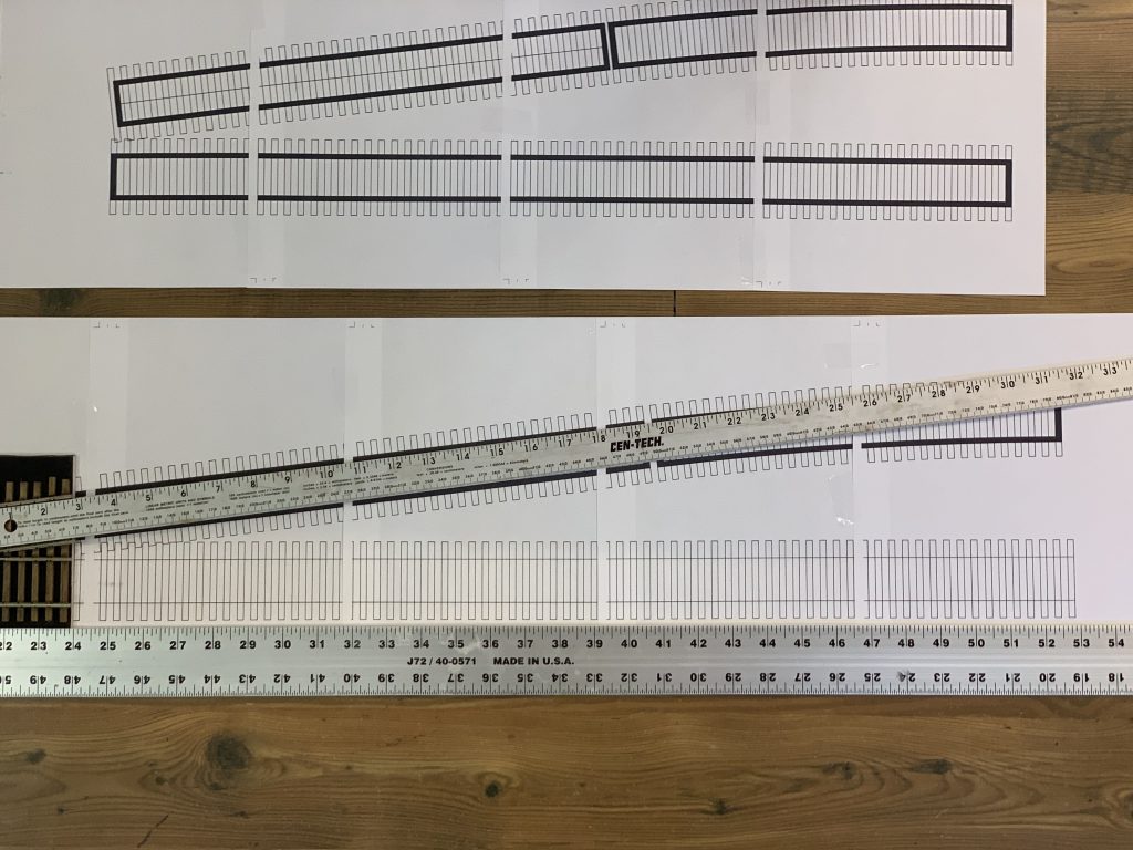
I have continued to work on the design for the diverging routes template. I was hoping to laser cut the template, but can’t resolve issues with my friend’s laser cutter so I’m cutting templates from .010” styrene.
I have also started to paint the #8 turnouts.

September 18, 2022
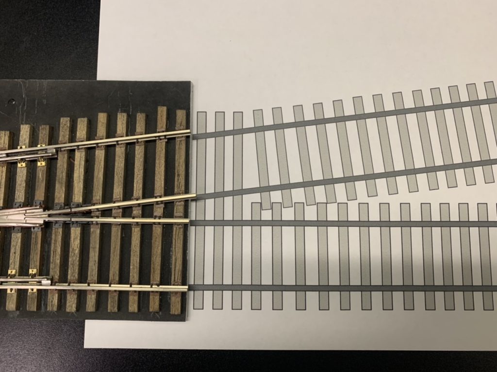
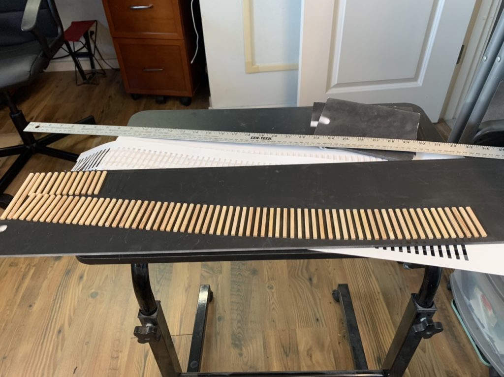
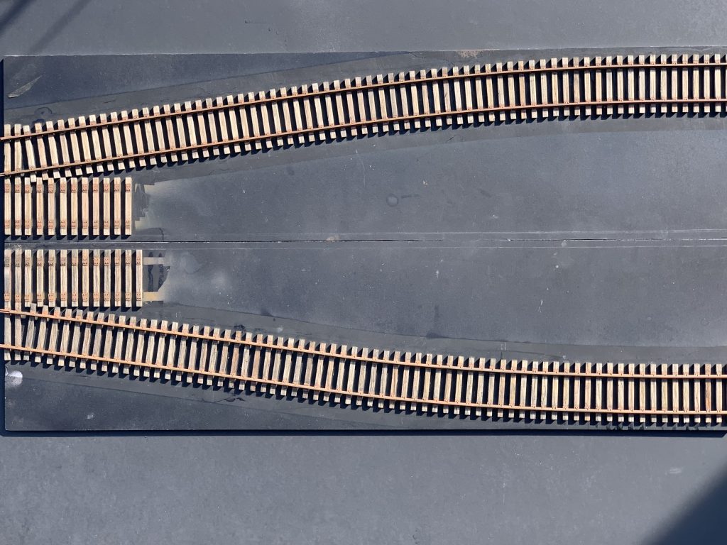
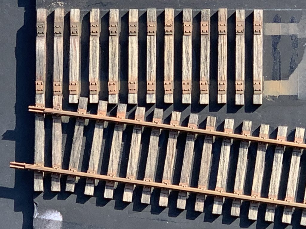
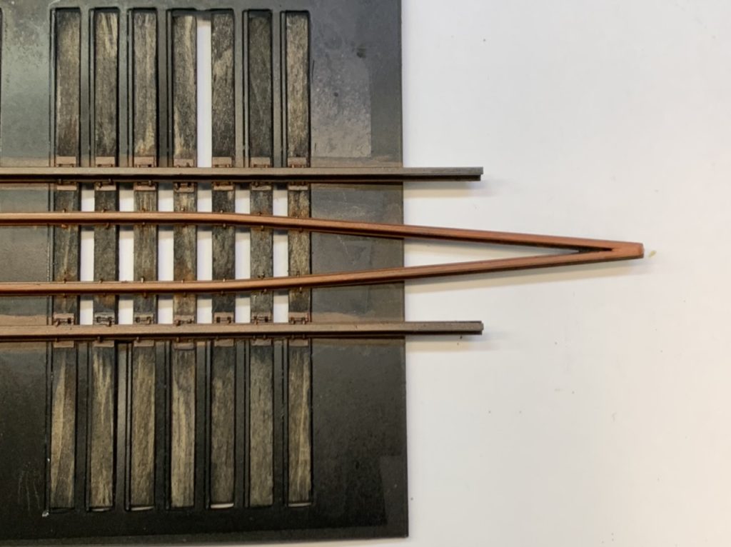
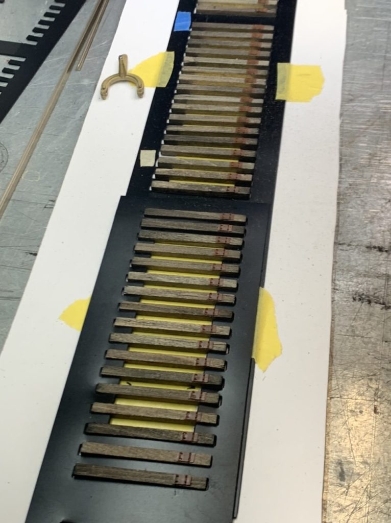
I have finalized the design for the diverging routes, cut a template and began to lay ties.
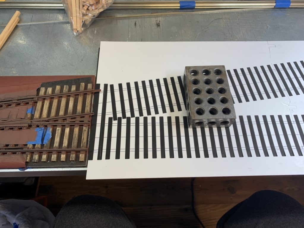
September 24, 2022
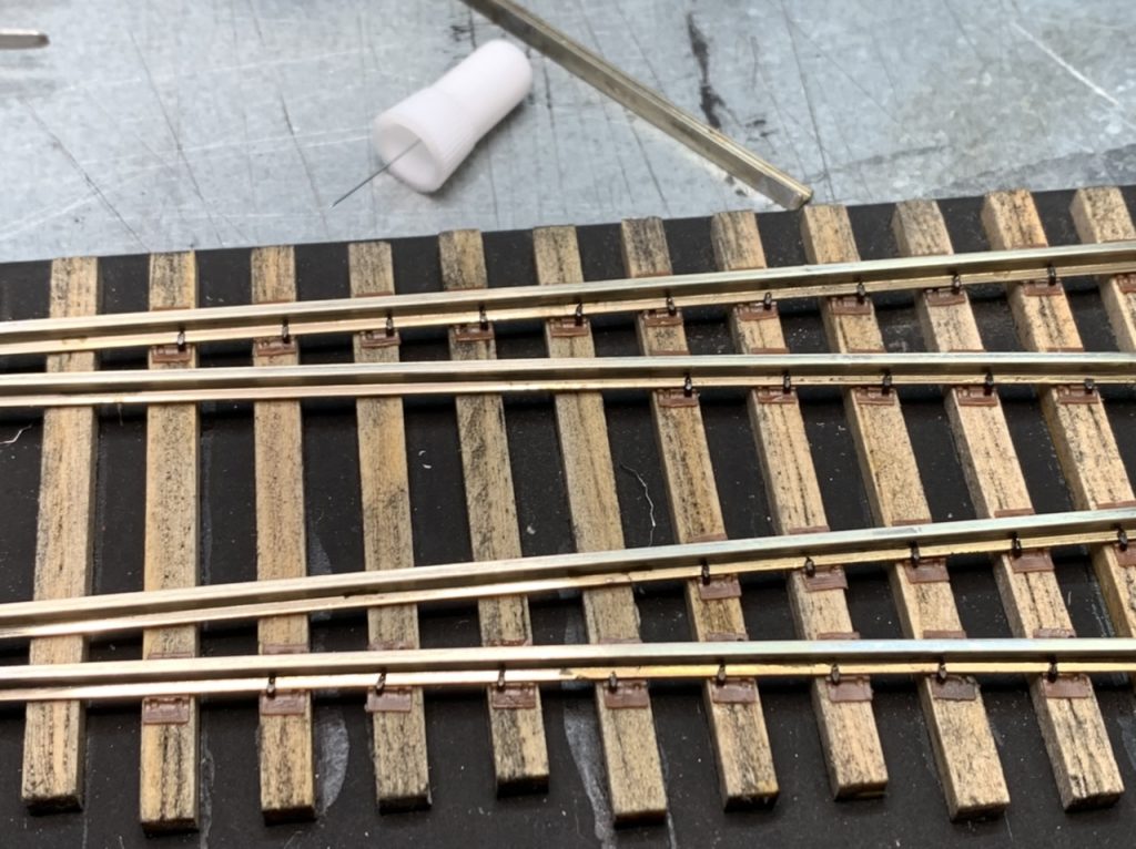
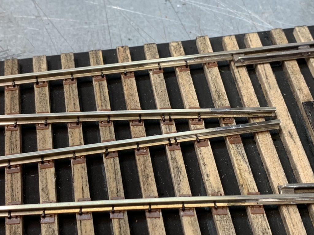
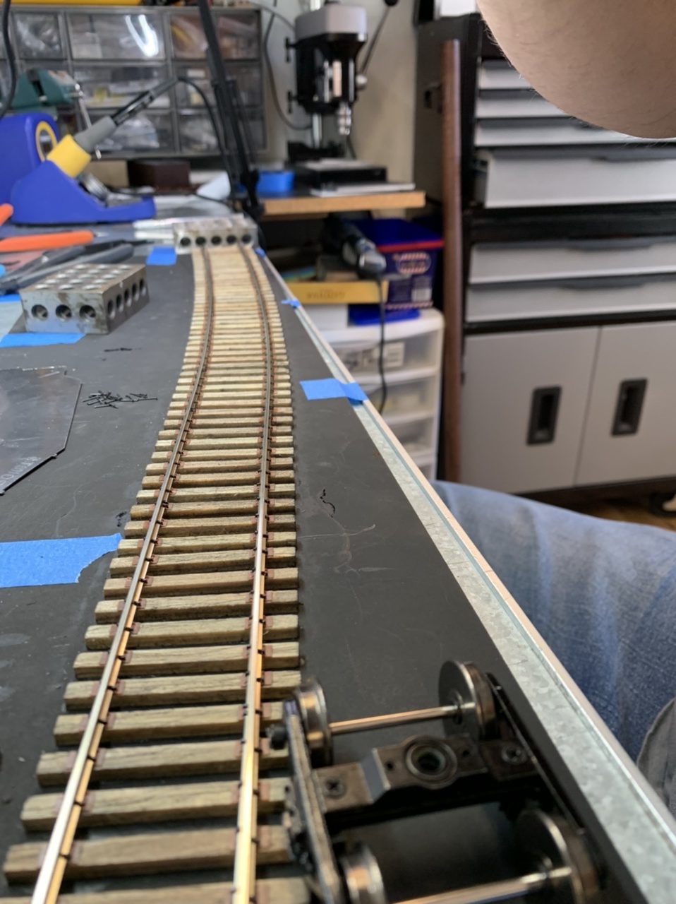
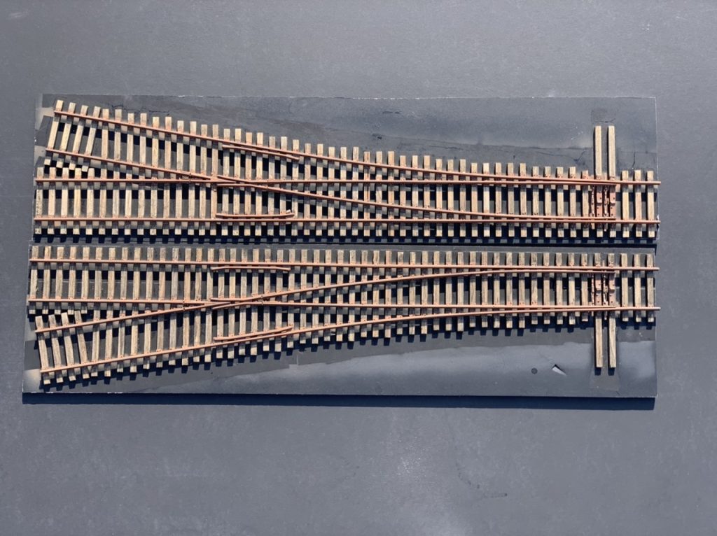
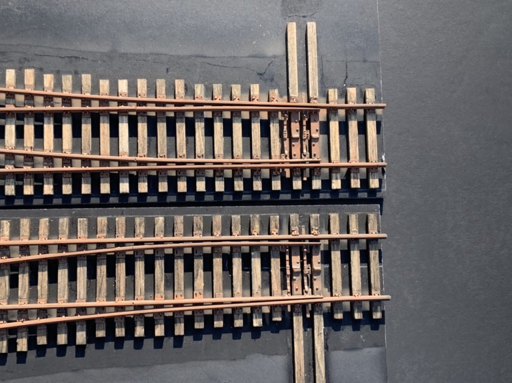
I am making real good progress. I finished sanding, staining, tie plates, rails and spiking the left hand diverging route. Also finished ties sanding, staining, and tie plates on the right hand diverging route. I finished ties, plates, rails, spiking and began staining the small bridge.
September 26, 2022
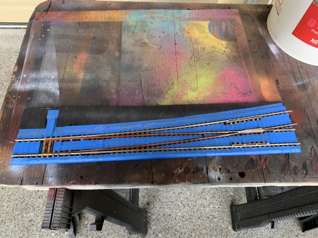
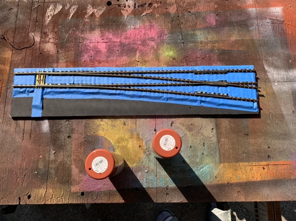
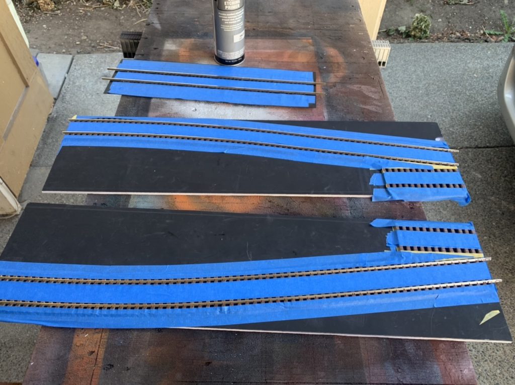
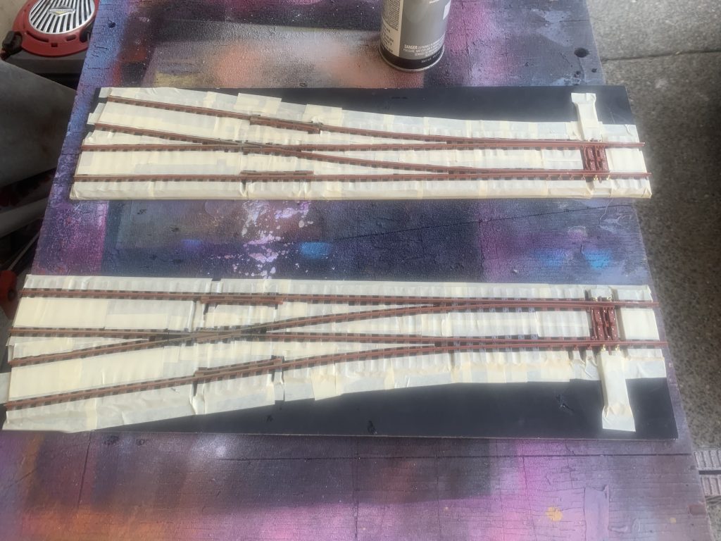
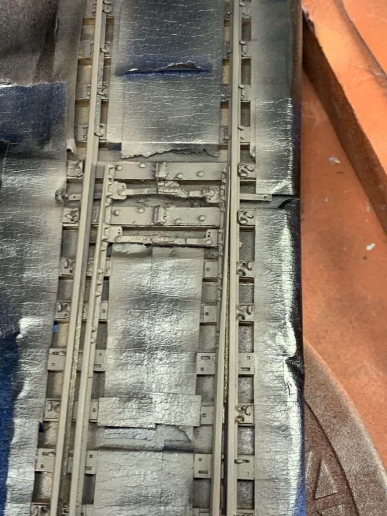
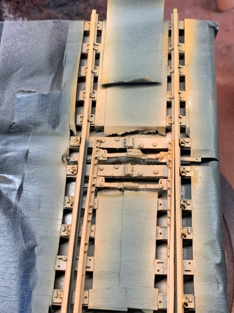
I completed spiking the right diverging section. I masked both diverging sections and the small bridge track section to paint the rails. I primed the rails on all three sections.
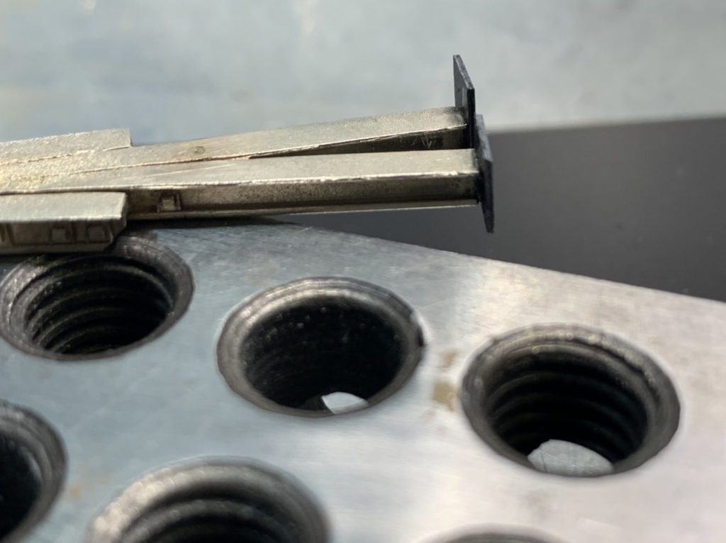
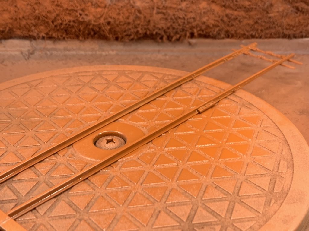
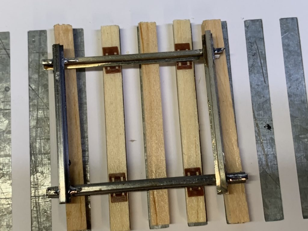
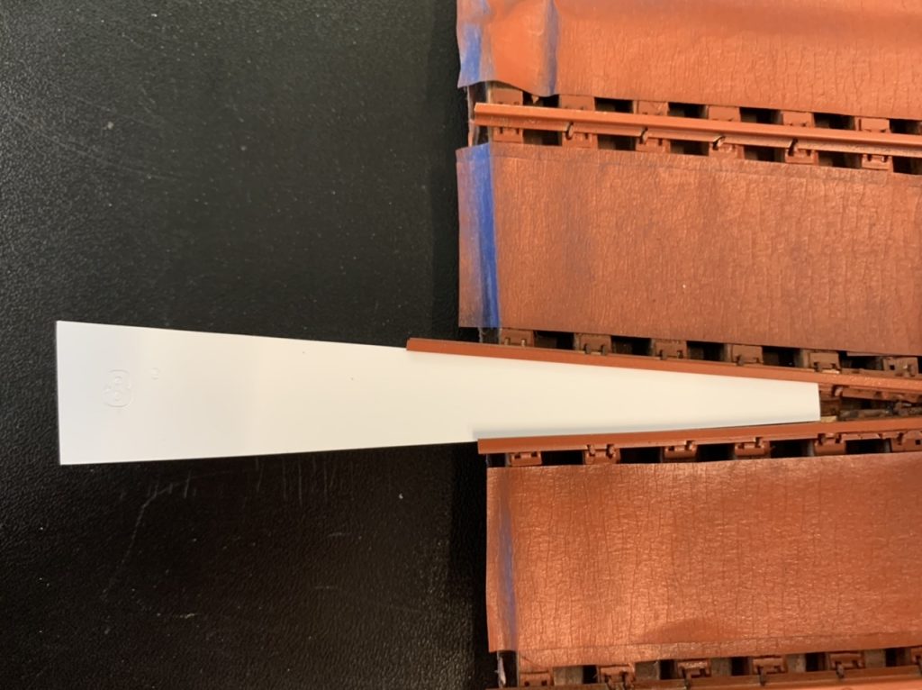
I am designing the bridge guard rails and making tools to build and install them. The design uses a 5 degree can’t at the ends. I’m going to work on these a little more still.
September 28, 2022
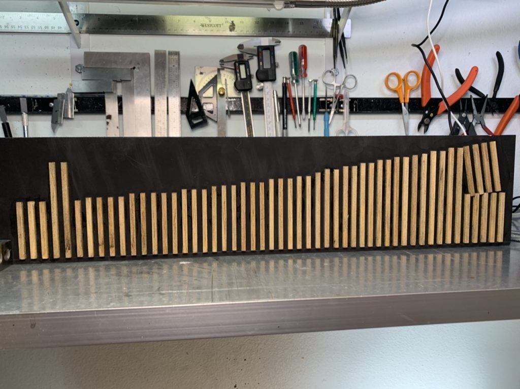
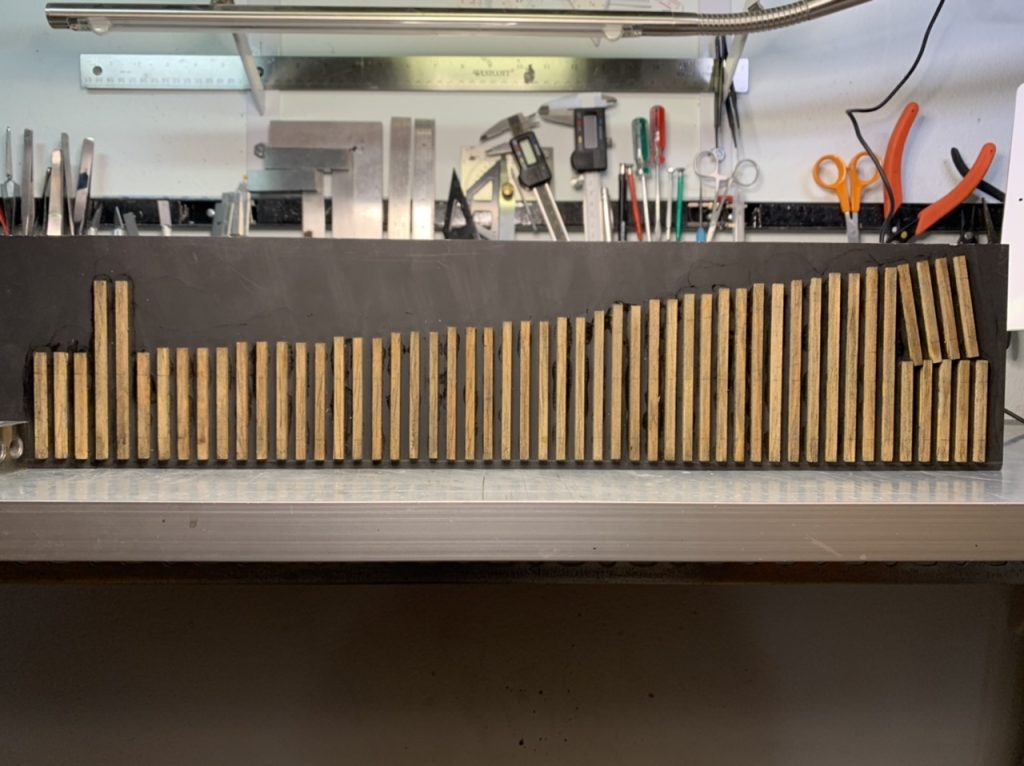
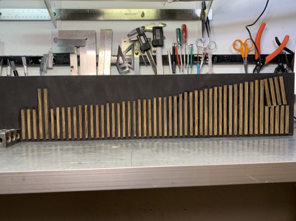
I’m making preparations for the long bridge. Pre-staining ties and removing tie plates from the sprues.
October 7, 2022
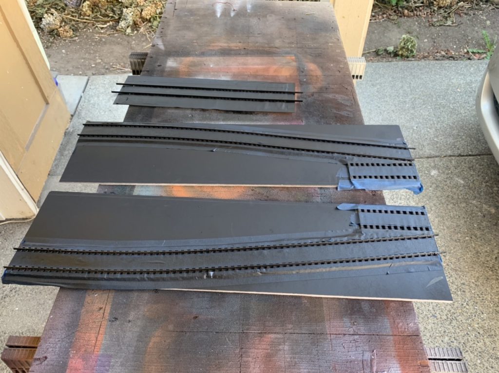
I finished separating another 400 tie plates from the sprues. I am continuing to prestain ties for the large bridge. I finished painting the diverging track pieces and have masked the #6 turnouts for painting.
October 9, 2022
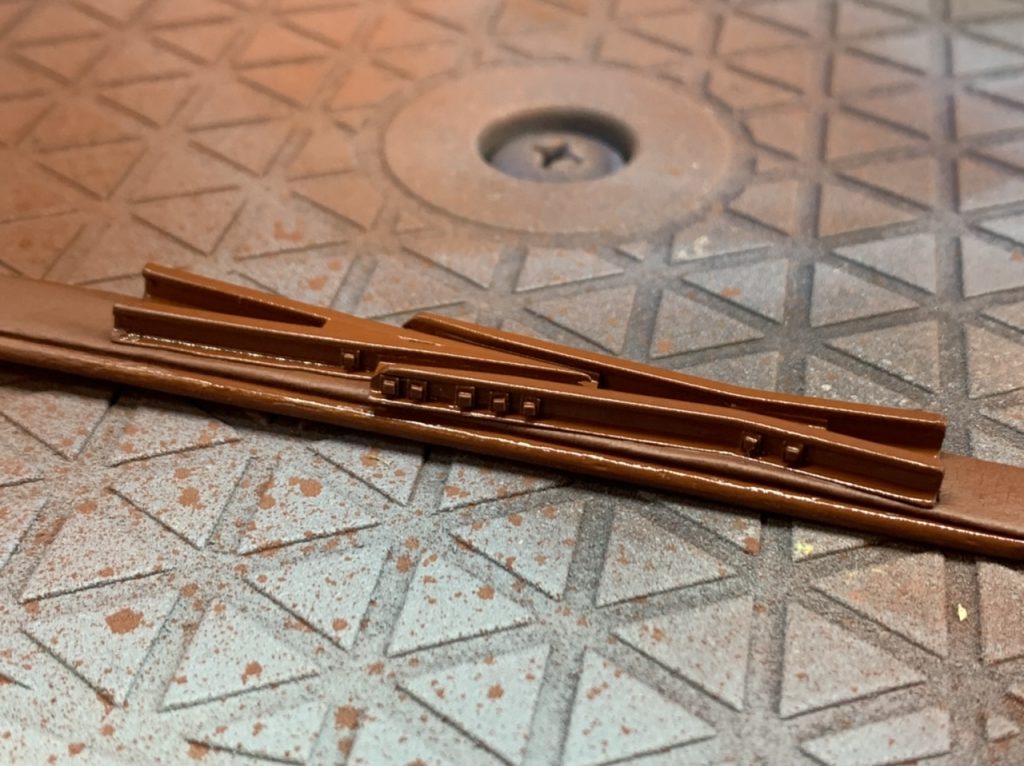
I have finished painting the turnouts.
October 20, 2022
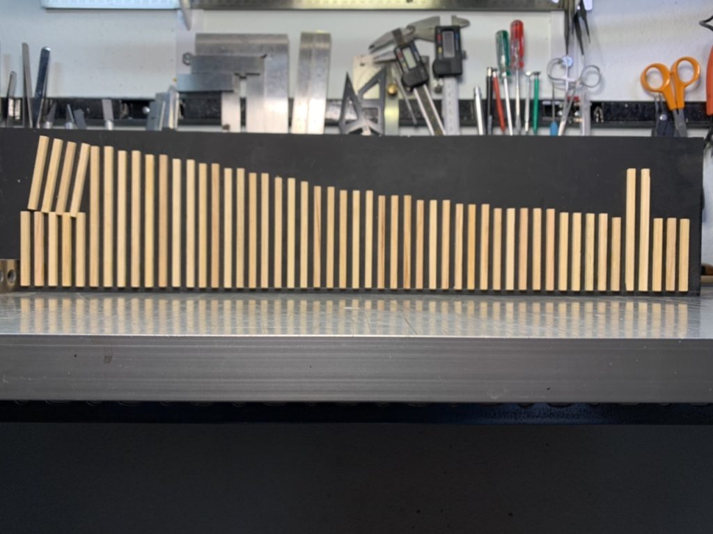
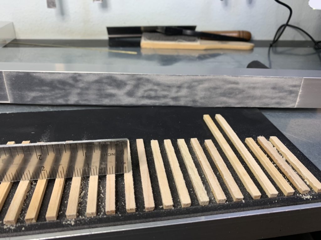
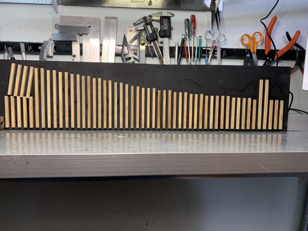
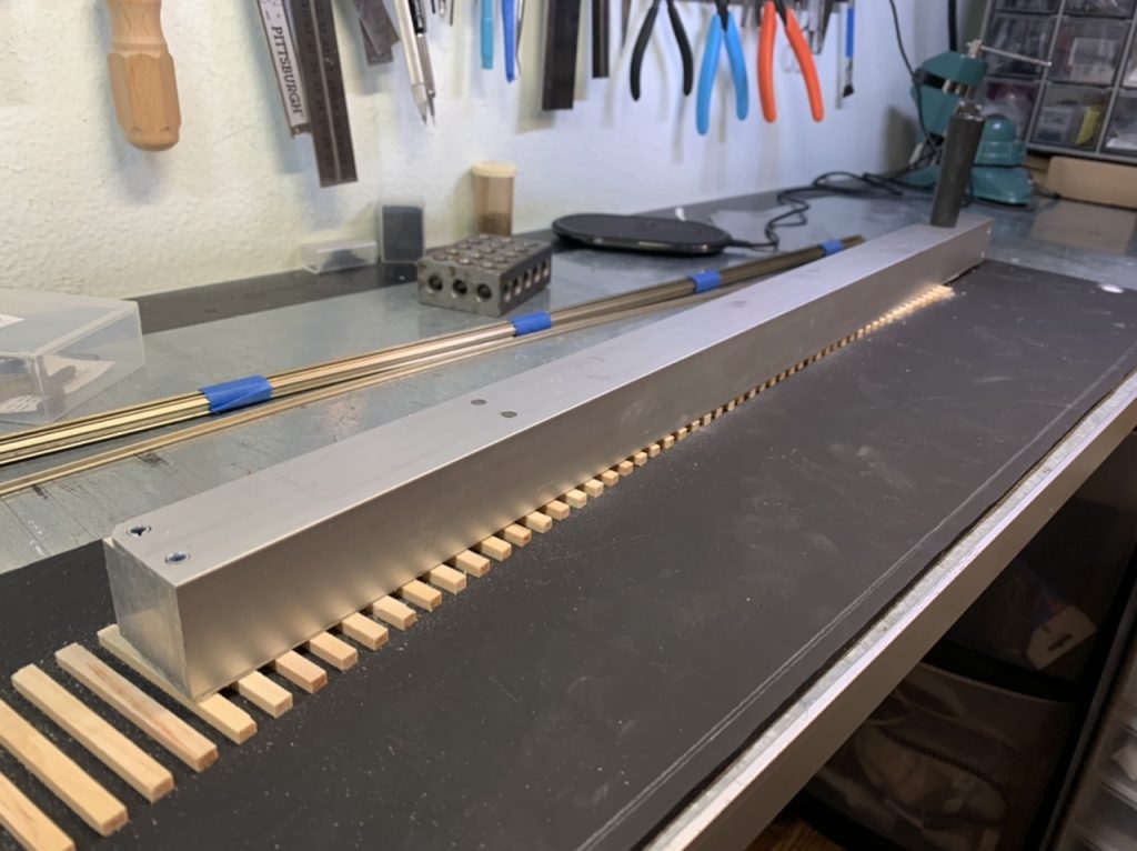
I cut the low profile ties. Finished pre-staining the large bridge ties. Cut the large bridge template.
October 21, 2022
I finished spiking and painting the guard rails for the small bridge.
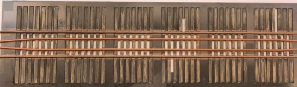
October 23, 2022
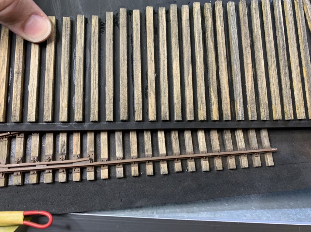
I started building the first half of the large bridge track. Laid ties and some tie plates, prepped the rail, painted the rail. Also made a new tool for making the guard rails (the old one was too short)
November 7, 2022
I’ve finished spiking and painting the large bridge sections and am now working on the large bridge guard rails.
November 13, 2022
I finished spiking the large bridge guard rails and am in the process of painting touch up. If I calculated correctly, the whole bridge has about 800 spikes.
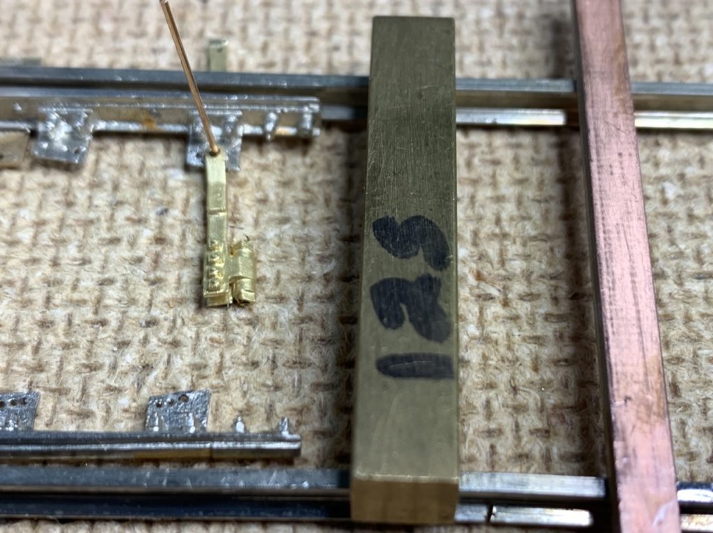
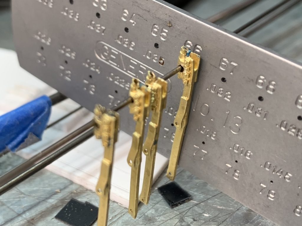
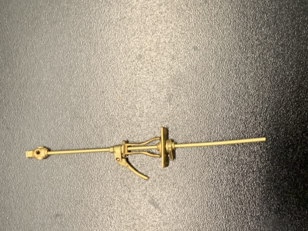
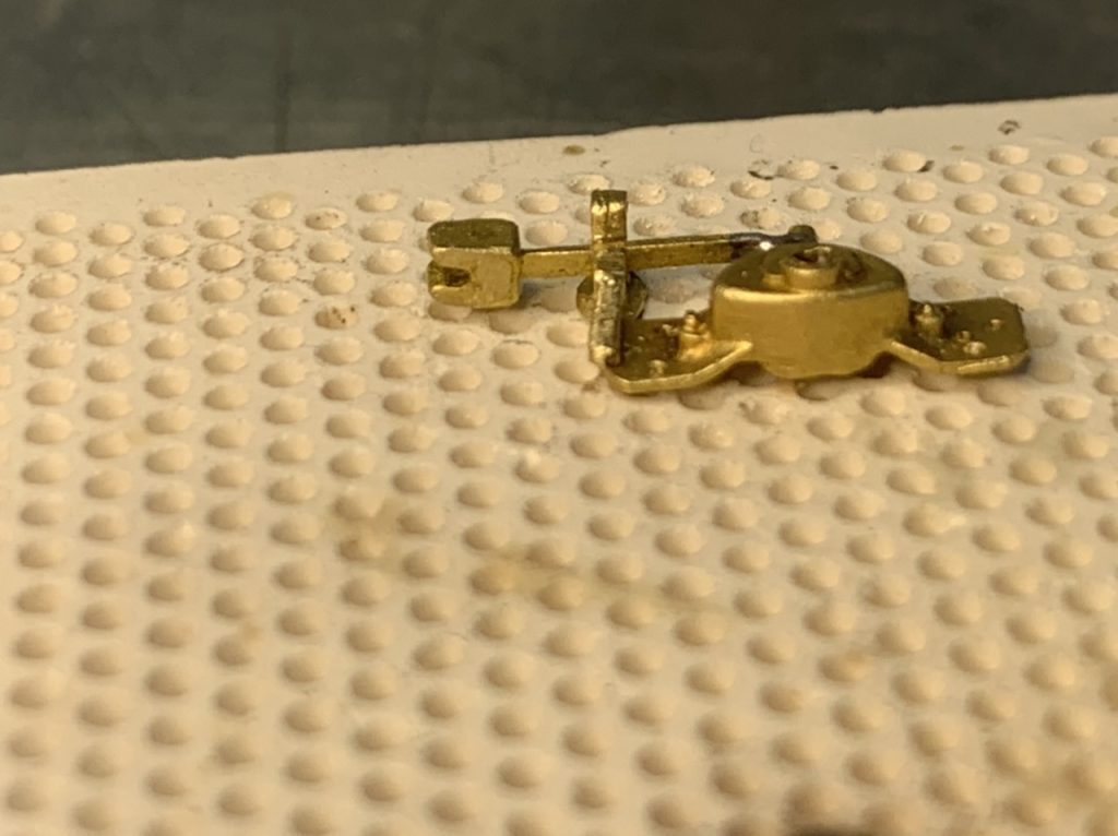
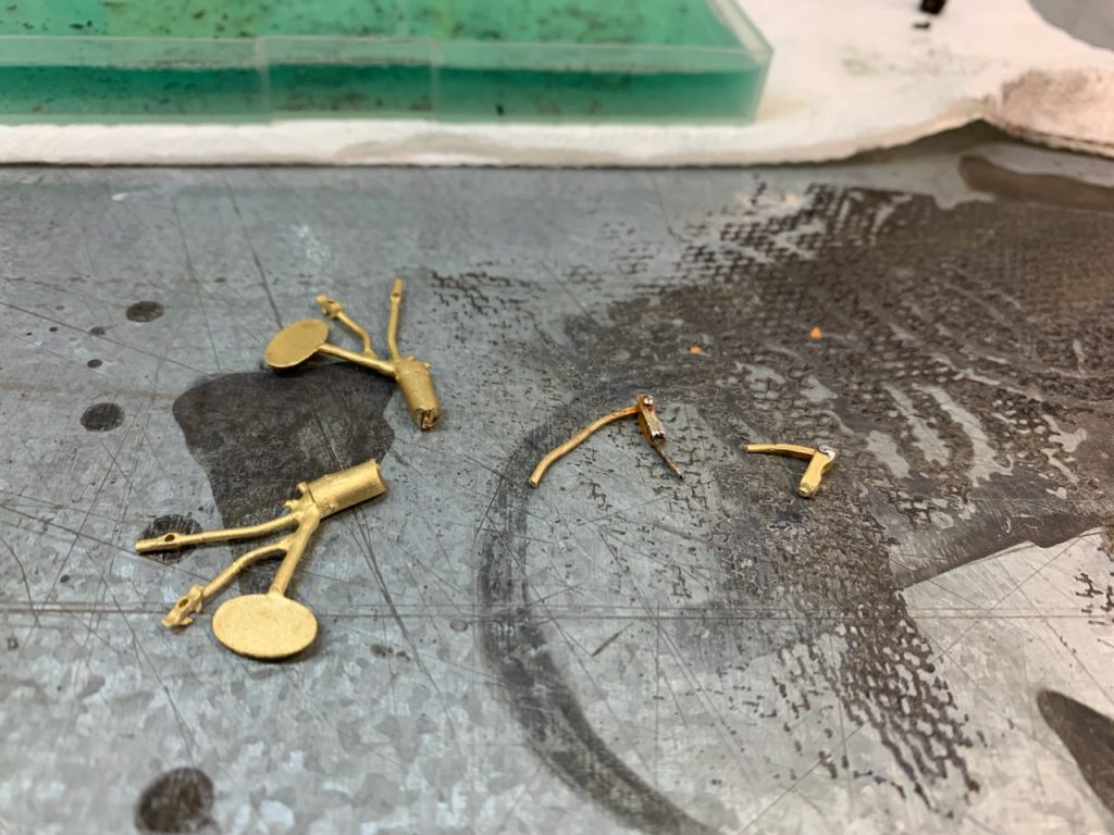
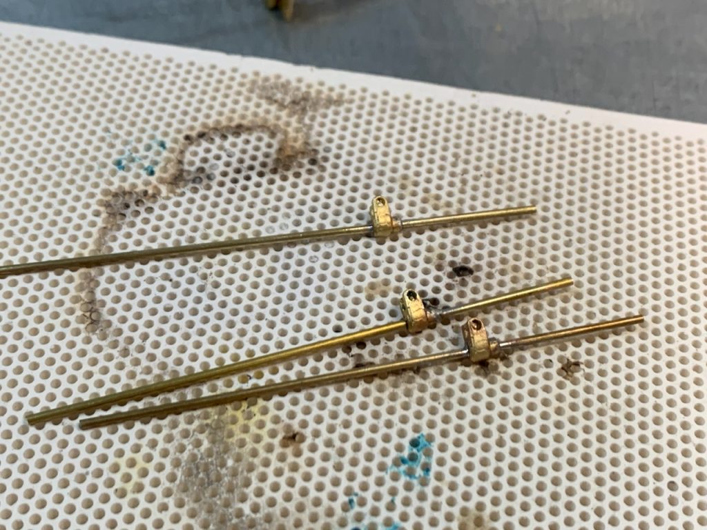
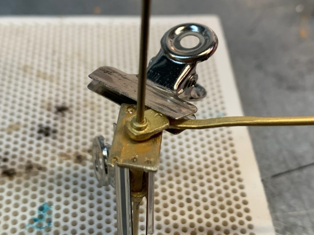
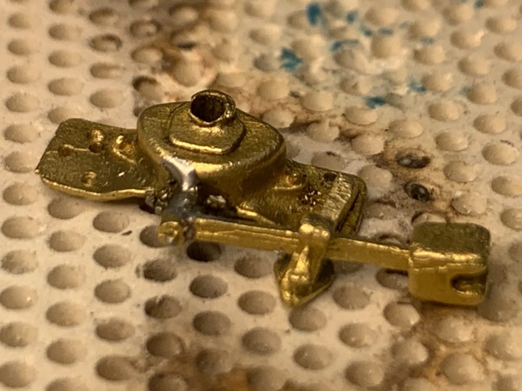
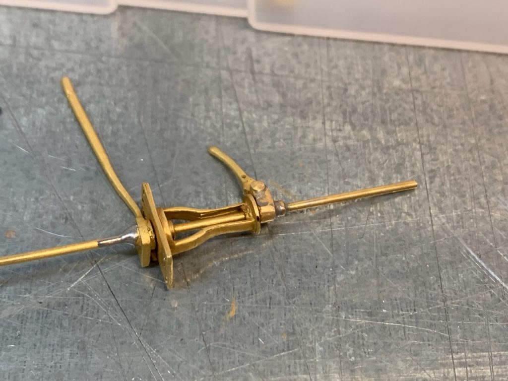
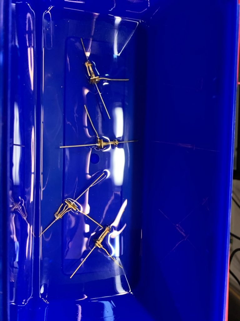
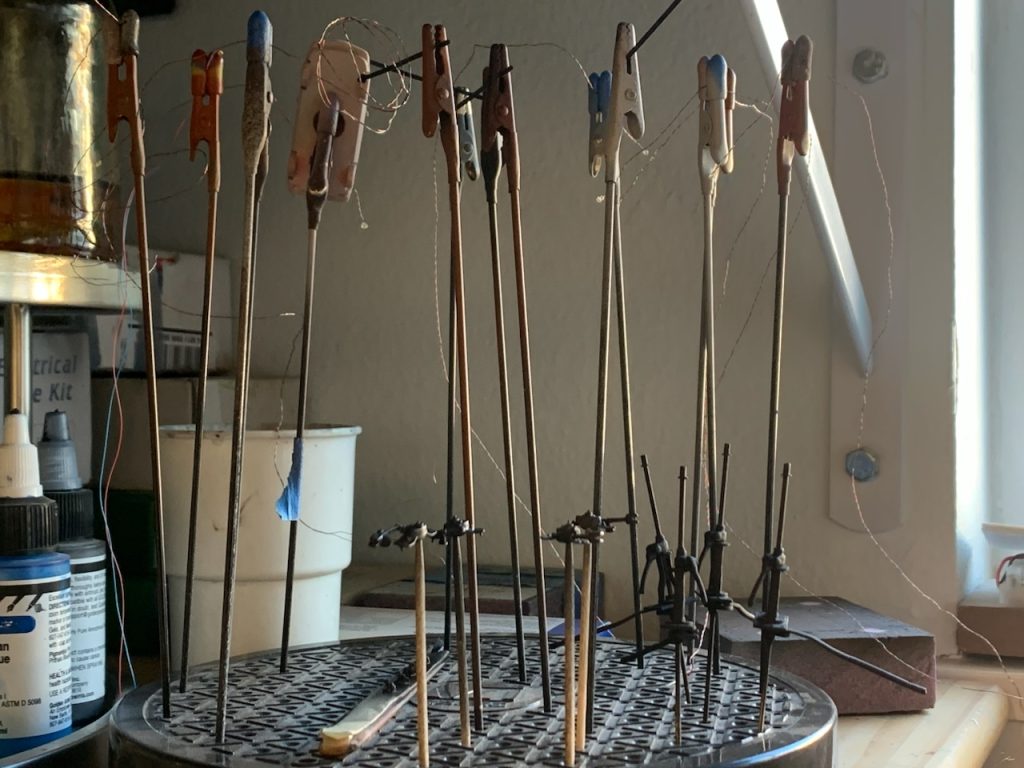
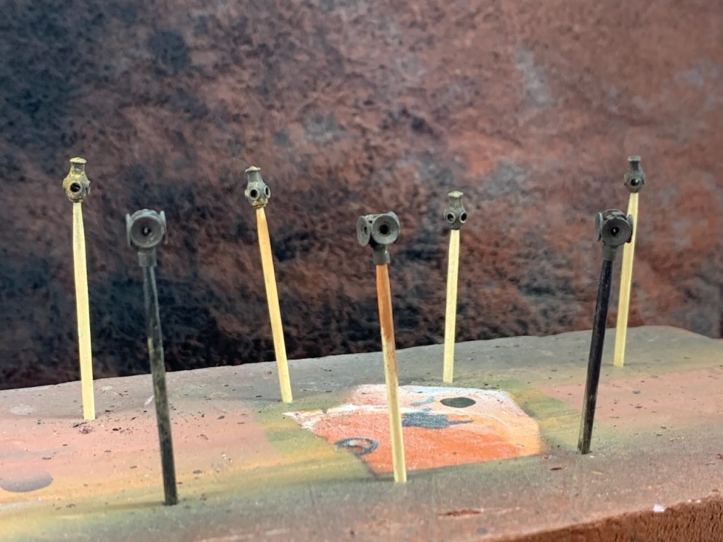
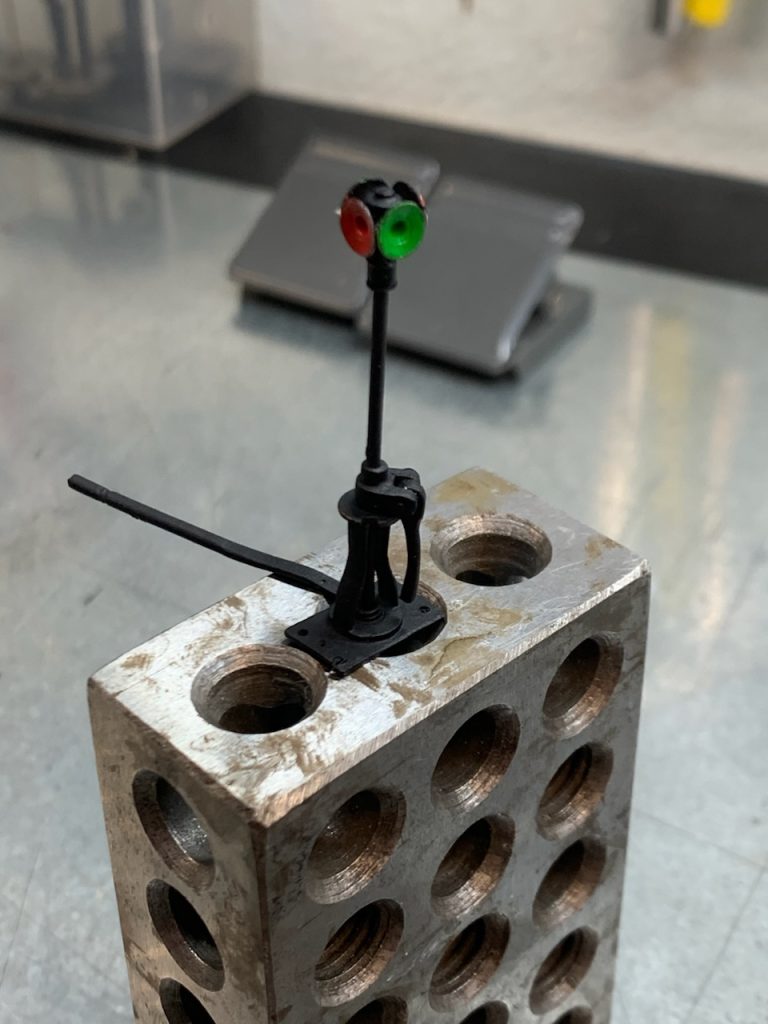
I have begun work on the switch stands. This involves filing the parts and reaming them to get the parts to fit correctly. Then soldering the parts together.
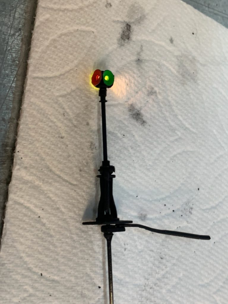
I spent a couple days working on rotating switch targets, using the proto:87 stores working switch stand indicator. (http://www.proto87.com/product2355.html)
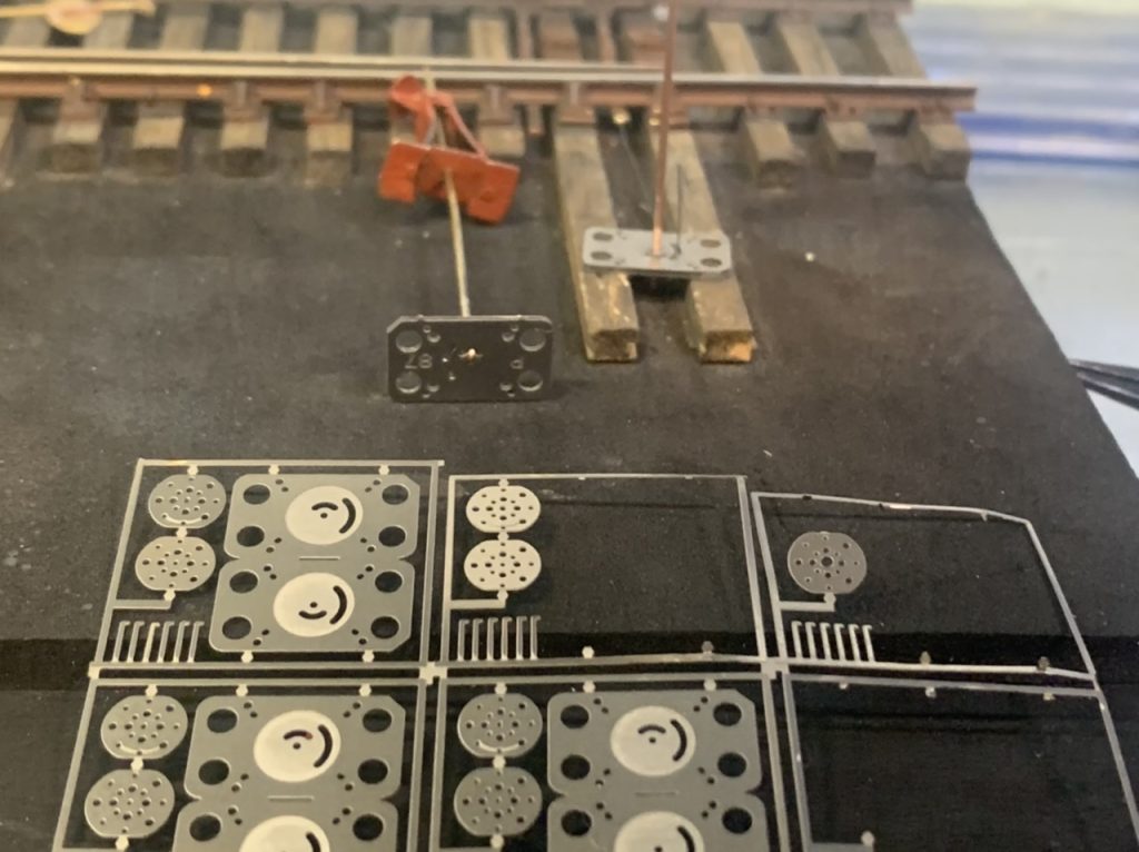
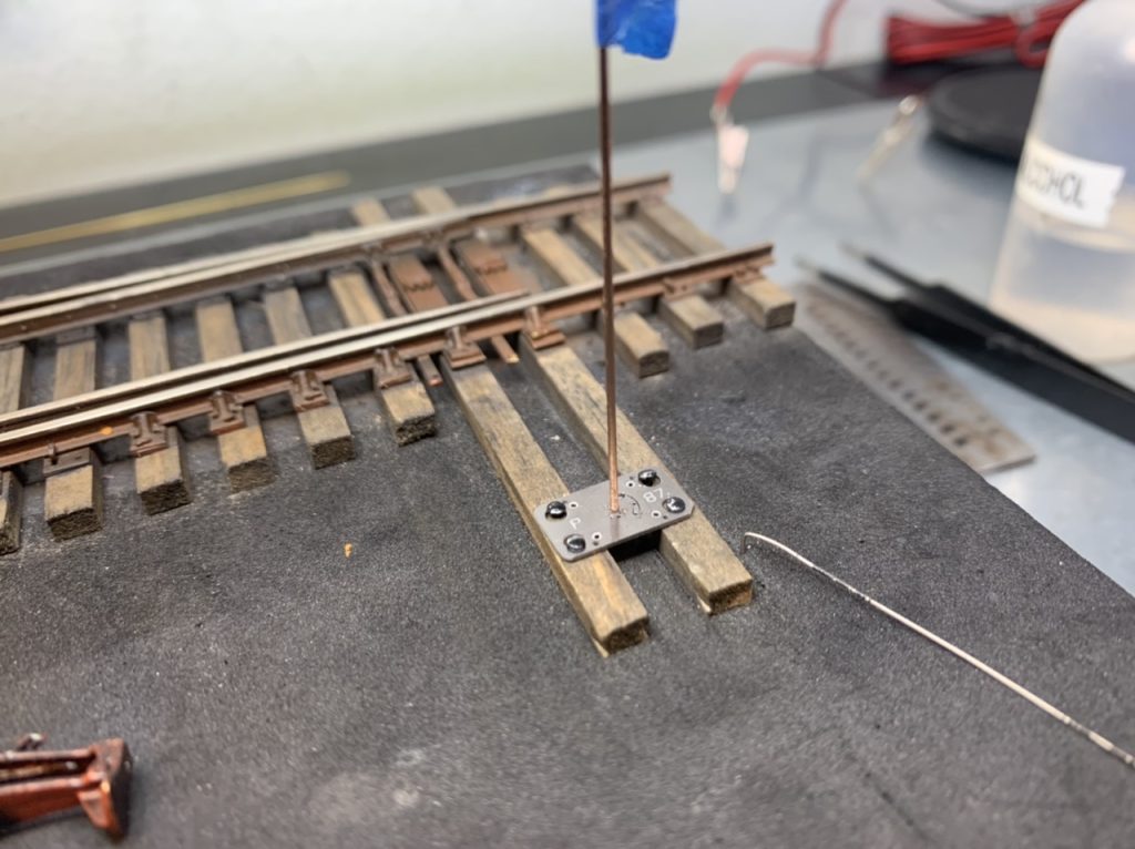
Unfortunately I was unable to adapt the proto87 switch stand indicator to our needs.
Given the tools and parts I am working with I don’t think I’ll be able to fabricate a reliable mechanism to rotate the targets 90 degrees. It may have to be accomplished by installing a mechanism below the bench work. I’ll leave the rod extra long to protrude below the layout.
December 4, 2022
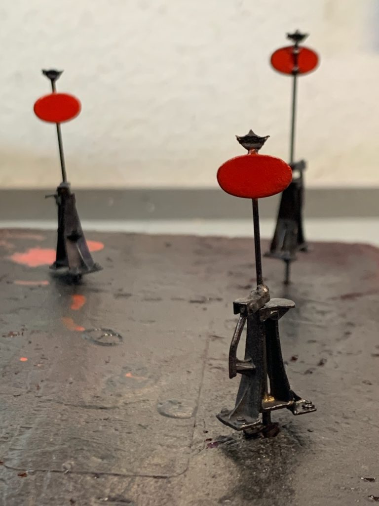
I’ve spent the last couple weeks building the switch stands. The switch stands are complete, some prices will be left for you to install in place.
I am reviewing my work before I complete it. The gap for one of the turnouts points was too small so I took it apart and am redoing it.
After completing the switch stands I wanted to make sure I reviewed the previously completed track work before completing the project. The points on one turnout were not gapped correctly. I too that turnout apart and re set the throw bars.
At this point I believe the project is complete.
- 2 #6 Turnouts
- 2 #8 Turnouts
- 2 #8 Diverging Track Sections
- Short Bridge
- Long Bridge
- 4 High Lighted Switch Stands
- 4 Low Lighted Switch Stands
- 2 High Unlit Switch Stands
I’ll double check everything and figure out how I’m going to package and ship it.